
 English
 中文简体
 русский
 Español
 Português
 عربى
Product Consultation
Your email address will not be published. Required fields are marked *
If you have ever measured a hydraulic cylinder bore, checked a tube drawing before machining, or tried to work out the force a cylinder can produce, you have already met the cross section of a cylinder formula. The idea sounds like pure geometry, but it sits behind everyday decisions in a hydraulic cylinder shop: how much oil pressure acts on the piston, how large the rod should be, and how much wall thickness the tube needs.
The formula itself is not difficult. What catches people out is that a cylinder does not have just one cross section. A horizontal slice, a vertical slice, an angled slice, and a slice through a hollow tube all give different shapes and different areas. Once you know which cut you are dealing with, the numbers become much easier to trust.
Content
In geometry, a right circular cylinder is defined by a radius r, a diameter d, and a height h. A cross section is the shape you see when a flat plane cuts through that cylinder. For a solid cylinder, the three most useful cases are a cut perpendicular to the axis, a cut through the axis, and an oblique cut at an angle.
For a hydraulic cylinder, the same idea applies, but the cylinder is usually hollow. The tube has an outer diameter and an inner bore, and the piston rod may pass through part of the internal space. That is why the annulus, or ring-shaped area, is often more important than the simple solid-circle formula.
When the cutting plane is perpendicular to the cylinder axis, the cross section is a circle. Its area is:
A = π × r2 = π × d2 / 4
This is the formula most people mean when they ask for the cross section of a cylinder formula. If the bore diameter is 100 mm, the radius is 50 mm, and the area is π × 50² = 7,854 mm², or about 78.5 cm². At a working pressure of 20 MPa, that area produces a theoretical force of roughly 157 kN. That direct link between area and force is why bore size matters so much in cylinder selection.
Using diameter is often more practical in a workshop because bore sizes are usually given as diameters. Just remember that the diameter must be divided by two before it is squared, or you must use the d² / 4 version of the formula.
If the plane passes through the axis of the cylinder, the cross section is a rectangle. The width is 2r, or d, and the height is h, so the area is:
A = 2 × r × h = d × h
This rectangle is not the area that oil pressure acts on inside a cylinder. It is still useful, though. It helps visualize wall thickness, port positions, mounting features, and the layout of a cylinder in a technical drawing. In CAD work, an axial section is often the quickest way to check whether a rod, tube, and end cap fit together as intended.
When the cutting plane is tilted, the cross section becomes an ellipse. The exact axes depend on the angle. For a plane tilted by θ from the perpendicular cut, one semi-axis remains r, while the other becomes r / cos θ. The area is then π × r² / cos θ. At θ = 0, the result returns to the familiar circle. As the cut becomes more slanted, the ellipse stretches and the area increases.
This case is less common in daily hydraulic calculations, but it is useful when reading angled sections on drawings or checking how a port or groove intersects a curved surface. It is also a good reminder that “cross section” only has a single answer after the cutting direction has been defined.
A hydraulic cylinder tube is a hollow cylinder. If the cut is perpendicular to the axis, the cross section is an annulus: a circle with a circular hole in the middle. For an outer radius R and an inner radius r, the area is:
A = π × (R2 − r2) = π × (D2 − d2) / 4
This is the formula we use most often when discussing cylinder tubes, because it separates the metal wall from the open bore. It is also the basis for the rod-side area when the inner diameter is the rod diameter rather than a tube bore. A common mistake is to treat wall thickness as an area; the wall thickness affects the outer and inner radii, but the area itself comes from the difference between the two circles.
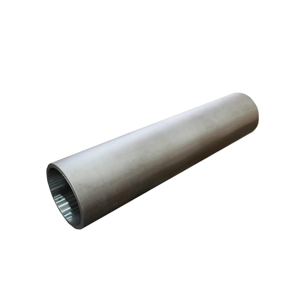 Cylinder Tube for Hydraulic Cylinder Bore and Wall GeometryHydraulic cylinder tube with a smooth, round inner surface, offered in Φ40–Φ320 mm diameters and lengths up to 8000 mm for bore and wall sizing.View Product →
In a double-acting cylinder, the piston has two different effective areas. On the bore side, pressure acts on the full circular area. On the rod side, the rod takes up part of that circle, so the effective area is the annulus:
Arod side = π × (D2 − drod2) / 4
With a 100 mm bore and a 60 mm rod, the bore area is 7,854 mm², the rod area is 2,827 mm², and the rod-side annulus is about 5,027 mm². At the same pressure, the retract force is lower than the extend force. That difference is not a flaw; it is a direct result of the geometry.
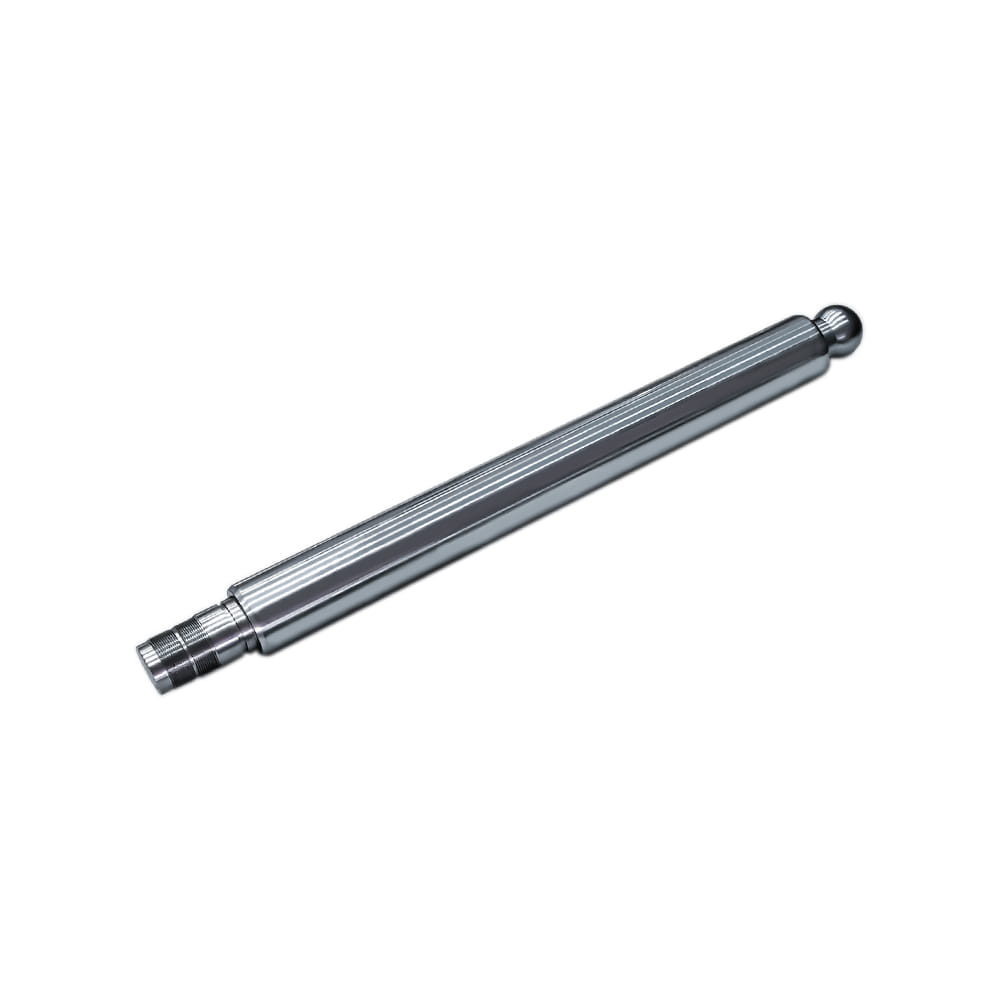 Chrome-Plated Piston Rod for Hydraulic Cylinder Force TransmissionConnecting rod that transmits piston force and supports reciprocating motion, available in 20–220 mm diameters with chrome plating and lengths to 8000 mm.View Product →
The bridge between geometry and hydraulic performance is the simple force equation:
F = p × A
Here, p is the pressure and A is the effective cross-sectional area. If pressure is in N/mm² and area is in mm², the force comes out in newtons. Unit consistency matters more than the formula itself. Mixing millimetres with centimetres, or bar with MPa, is a far more common source of error than choosing the wrong circle formula.
When we review a new cylinder request, we check bore area, rod area, stroke, pressure, and mounting conditions together. The area calculation is only one part of the picture, but it is a part that should be clear before any drawing is finalized. For a broader view of the selection points, see our notes on key design considerations for hydraulic cylinders.
At Zhejiang Huanfeng Machinery, we have been designing and producing hydraulic cylinders since 2004 for cranes, aerial work platforms, special vehicles, piling machinery, and other demanding applications. In that work, the cross-section formula is not an abstract exercise. It helps our team match bore size to force, choose rod diameters that resist buckling, and confirm that tube wall thickness is suitable for the pressure rating.
The same geometry also supports seal selection. A seal groove, a piston land, and a rod shoulder all depend on diameters and effective areas. If the bore or rod dimension is misunderstood, the error can travel through the whole design. That is why we prefer to confirm the basic circle and annulus values early, then build the rest of the cylinder around them.
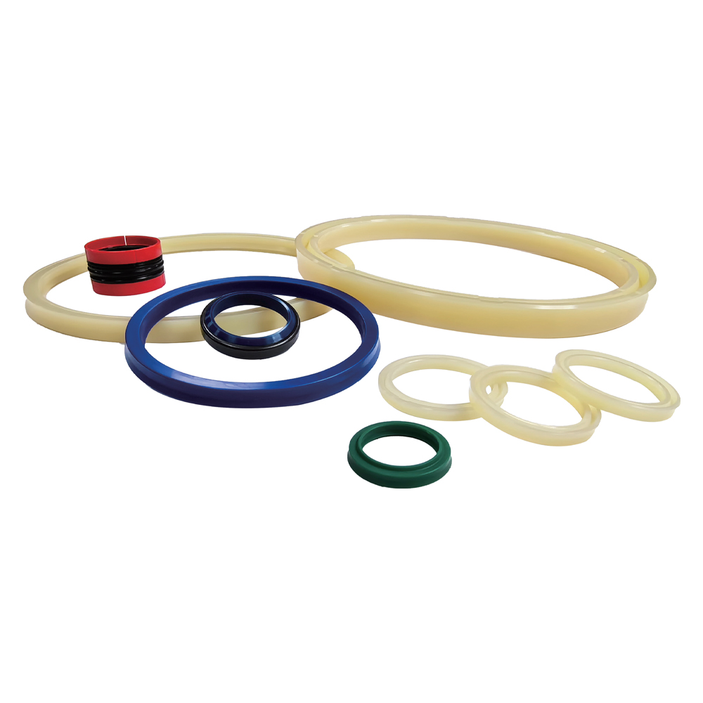 Hydraulic Cylinder Seals for Leakage Control and Pressure StabilitySeals for hydraulic cylinder chambers, available for Φ40–Φ320 mm bores and Φ20–Φ220 mm rods, helping prevent internal and external oil leakage.View Product →
| Cut direction | Shape | Area formula | Typical use in cylinder work |
|---|---|---|---|
| Perpendicular to axis | Circle | πr² = πd² / 4 | Bore area and extend force |
| Through the axis | Rectangle | 2rh = dh | Wall thickness and drawing checks |
| Oblique to axis | Ellipse | πab, depending on angle | Angled sections and port checks |
| Perpendicular, hollow | Annulus | π(R² − r²) = π(D² − d²) / 4 | Tube wall, rod-side area, seal grooves |
The cross section of a cylinder formula is simple, but it rewards careful reading. For a solid cylinder, the perpendicular cut gives πr², the axial cut gives a rectangle, and an angled cut gives an ellipse. For a hydraulic cylinder tube, the annulus formula π(R² − r²) is usually the one that matters most. Once those shapes are clear, bore size, rod diameter, wall thickness, and force calculations all become easier to discuss with confidence.
If you are working through a cylinder specification and want a second pair of eyes on the bore, rod, or tube dimensions, our team is always glad to talk through the application rather than just quote a part number.
Your email address will not be published. Required fields are marked *
Marvelous Design Meets Rigorous Manufacturing
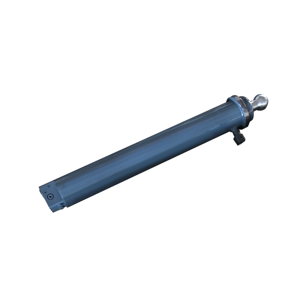 Scissor Lift Aerial Platform Hydraulic Outrigger Cylinder
Function: Firmly Supports the Vehicle: Ensures stability during operation. The ball-head foot automatically levels on slopes, while the integrated balance valve...
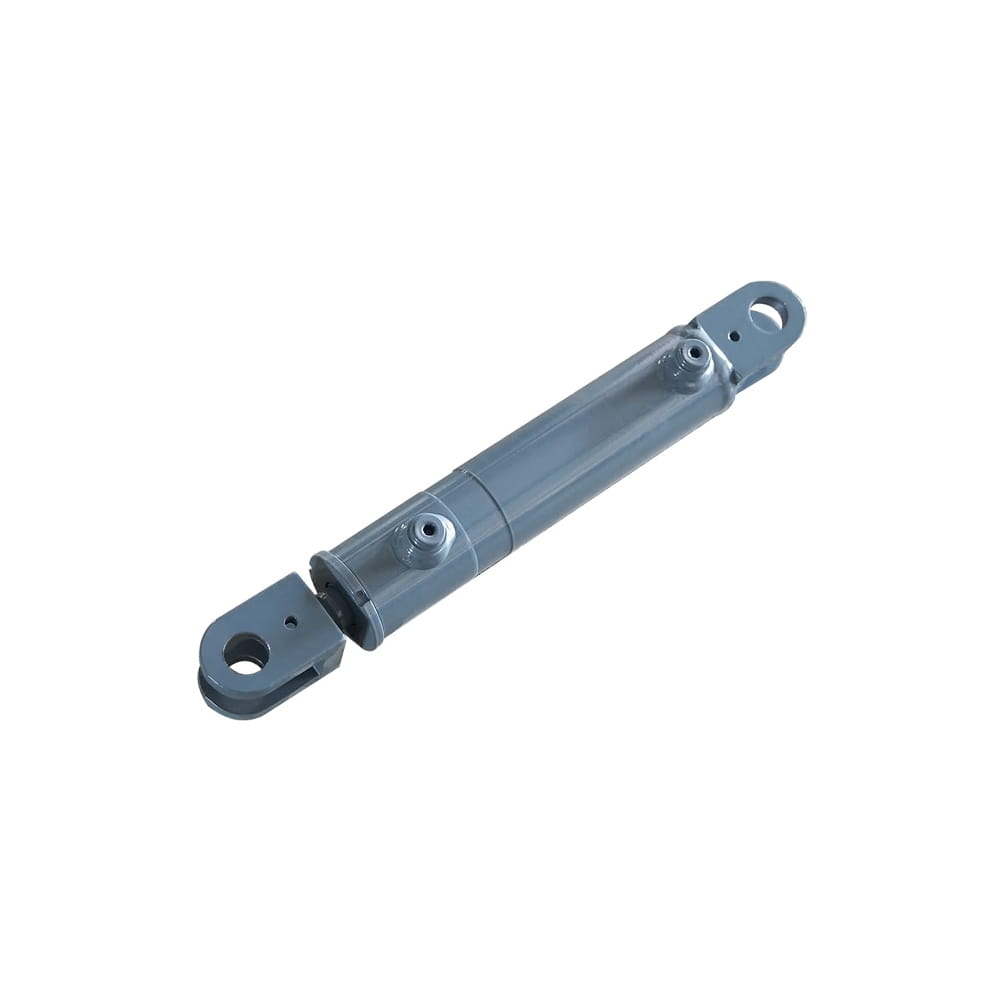 Scissor Lift Aerial Platform Hydraulic Steering Cylinder
Function: Connecting Chassis and Wheel Hub: Through hydraulic pressure, drives the piston rod to move, enabling precise wheel hub rotation. This ensures platfor...
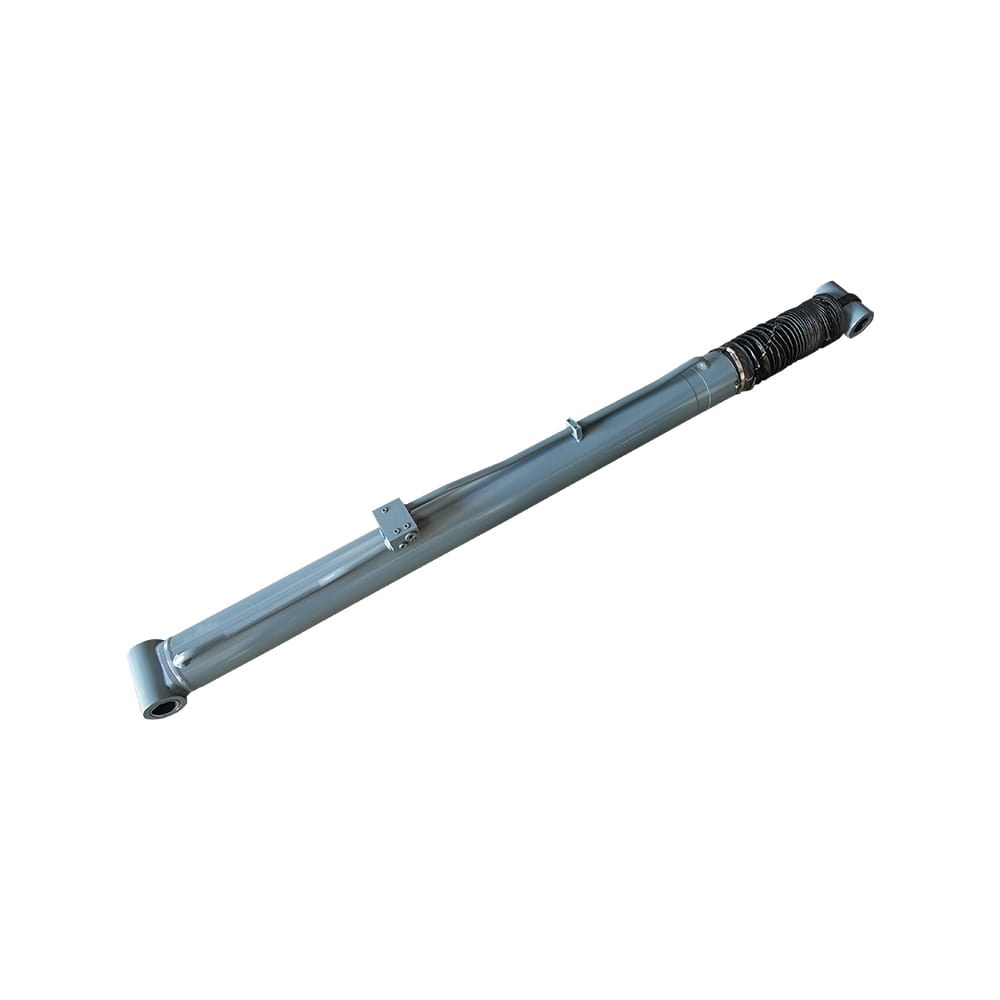 Boom Lift Aerial Platform Hydraulic Luffing Cylinder
Function: Adjust the angle of the telescopic arm to flexibly position the work platform at various heights and positions, meeting diverse aerial work requiremen...
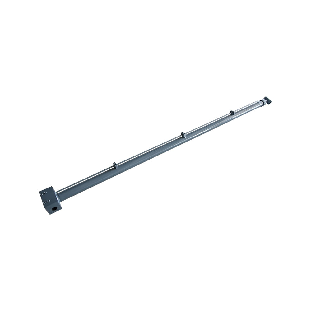 Boom Lift Aerial Platform Hydraulic Telescopic Cylinder
Function: Adjust the length of the arm to allow the aerial work platform to lift and move flexibly, ensuring range and height requirements.
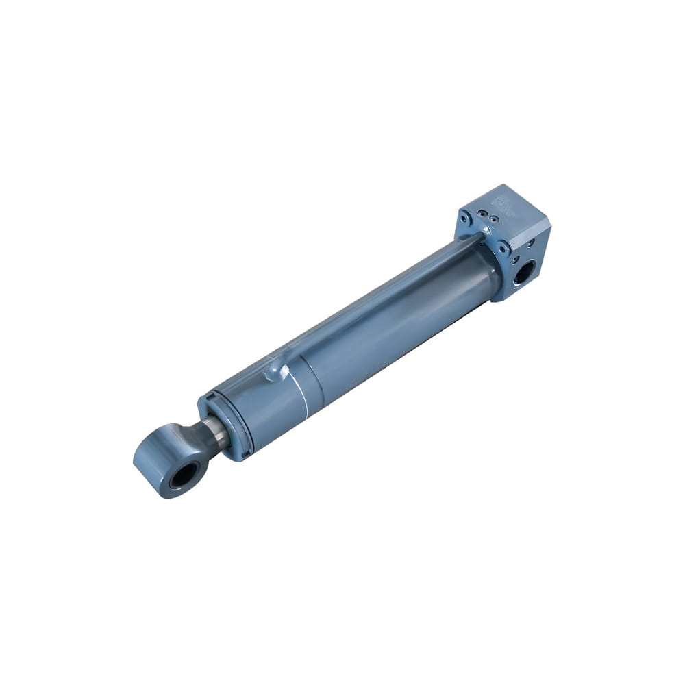 Boom Lift Aerial Platform Hydraulic Frame Leveling Cylinder
Function: Automatically adjust the chassis at the bottom of the platform to a level state, ensuring stable and wobble-free support in different terrains and wor...
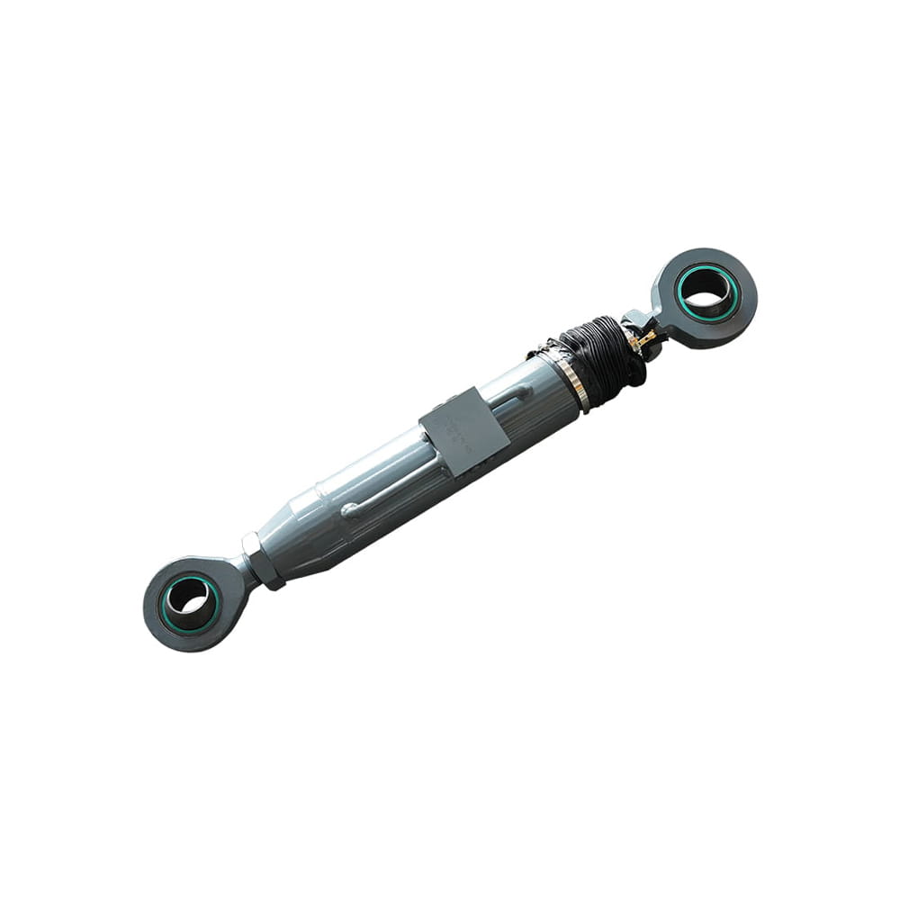 Boom Lift Aerial Platform Hydraulic Bridge Extension Cylinder
Function: An important design that enhances adaptability and working range. This function allows the platform to widen its chassis under specific conditions to ...
Copyright © by Zhejiang Huanfeng Machinery Co., Ltd. Rights Reserved.
