
 English
 中文简体
 русский
 Español
 Português
 عربى
Product Consultation
Your email address will not be published. Required fields are marked *
A hydraulic cylinder is a force multiplier in the simplest possible sense: a small pump and a modest bore can shift a load that no crew of people could move by hand. The arithmetic behind that multiplication is short — one formula, one area calculation, and a couple of unit conversions — but it is also exactly where most sizing mistakes hide. Whether you are checking a crane boom cylinder, a scissor lift, or a jacking cylinder for a pipe installation, the same handful of steps gets you a trustworthy answer.
Content
Force equals pressure multiplied by the area that pressure acts on: F = P × A. Pressure is the hydraulic fluid's push per unit of surface, and the piston area is how much surface it has to push against. Double one and you double the force; double both and you get four times as much.
In metric practice, the cleanest pairing is megapascals and square millimetres. Because one megapascal is one newton per square millimetre, the result lands directly in newtons — divide by 1,000 and you have kilonewtons. In imperial practice, pounds per square inch multiplied by square inches gives pounds of force with no conversion at all.
The values you will meet most often when converting between systems:
Write the units down before you start. Most wrong answers we see are not wrong formulas; they are bars fed into an equation expecting megapascals, or millimetres fed into one expecting centimetres.
On the extend stroke, full pump pressure acts on the whole bore area, so the area is π/4 × D², where D is the bore diameter. On the retract stroke the fluid only sees the ring-shaped area around the rod, so the effective area is π/4 × (D² − d²), with d being the rod diameter. The rod occupies metal that pressure cannot reach.
Take a 100 mm bore cylinder with a 70 mm rod running at 20 MPa. The full bore area is about 7,854 mm², giving roughly 157 kN of thrust. The annulus area is about 4,006 mm², giving roughly 80 kN of pull — barely half. A cylinder that lifts a load with authority may be quite tame when it has to pull the same load back.
This matters whenever the working load reverses direction during a cycle: a folding arm that pulls as well as pushes, a leveling cylinder that has to hold a platform down as well as up, or a stabilizer leg that must retract against resistance. Size on the weaker side, not the stronger one.
Suppose a machine needs to raise 8 tonnes steadily, and the pump relief is set at 20 MPa. Here is the sequence we would walk through with a customer.
That last step is where theory meets practice. A cylinder can be strong enough and still be the wrong cylinder, because the rod behaves like a column under compression and its safe load falls sharply as stroke length grows.
The number from F = P × A is theoretical. Real output is a little lower, and it is worth knowing why. Seal friction, guide friction, and the pressure needed to push oil back to tank all take a bite. For most mobile machinery, an efficiency of 0.85 to 0.95 applied to the theoretical figure gets you close to reality, with larger cylinders and higher pressures sitting toward the lower end of that range.
A useful form of the equation is: net force = (extend pressure × bore area) − (return-line pressure × annulus area) − friction. The middle term is easy to forget, and it can be significant on circuits with restricted return flow or counterbalance valves.
Pressure also needs care. The relief valve setting is a ceiling, not a promise. During fast extension, flow demand can outrun the pump and system pressure sags, so the force available at the moment you need it may be lower than the catalogue calculation suggests. Systems that hold a load for long periods, such as outrigger cylinders, should be checked for holding capability as well as moving capability.
The table below is a quick sanity check for common bore sizes. Values assume the full bore area on the extend stroke and ignore friction, so treat them as an upper bound rather than a working capacity.
| Bore (mm) | Bore area (cm²) | Thrust at 16 MPa (kN) | Thrust at 20 MPa (kN) |
|---|---|---|---|
| 63 | 31.2 | 49.9 | 62.4 |
| 80 | 50.3 | 80.4 | 100.5 |
| 100 | 78.5 | 125.7 | 157.1 |
| 125 | 122.7 | 196.3 | 245.4 |
| 160 | 201.1 | 321.7 | 402.1 |
The formula is universal, but the inputs are not. On a truck-mounted crane, the luffing cylinder's job is to hold the boom at a working radius, and the force it feels depends on the angle of the boom as much as on the load hanging from the hook. As the boom rises, the cylinder's moment arm changes, so the same lift can demand very different pressures. That is why luffing cylinders are specified by geometry and mounting as carefully as by bore.
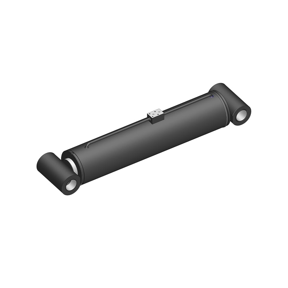 Truck-Mounted Crane Hydraulic Luffing CylinderFunction: Adjusting the Boom Angle: Through the extension and retraction of the luffing cylinder, the boom can tilt up and down to meet lifting needs at various height...View Product →
Scissor lifts sit at the other end of the spectrum. The lifting cylinder works through a linkage whose mechanical advantage shifts continuously as the platform rises, so the highest rod force often appears near the fully collapsed position rather than at full height. Large bore, modest pressure, and a short stroke are typical, and the calculation has to be repeated at several points in the lift curve.
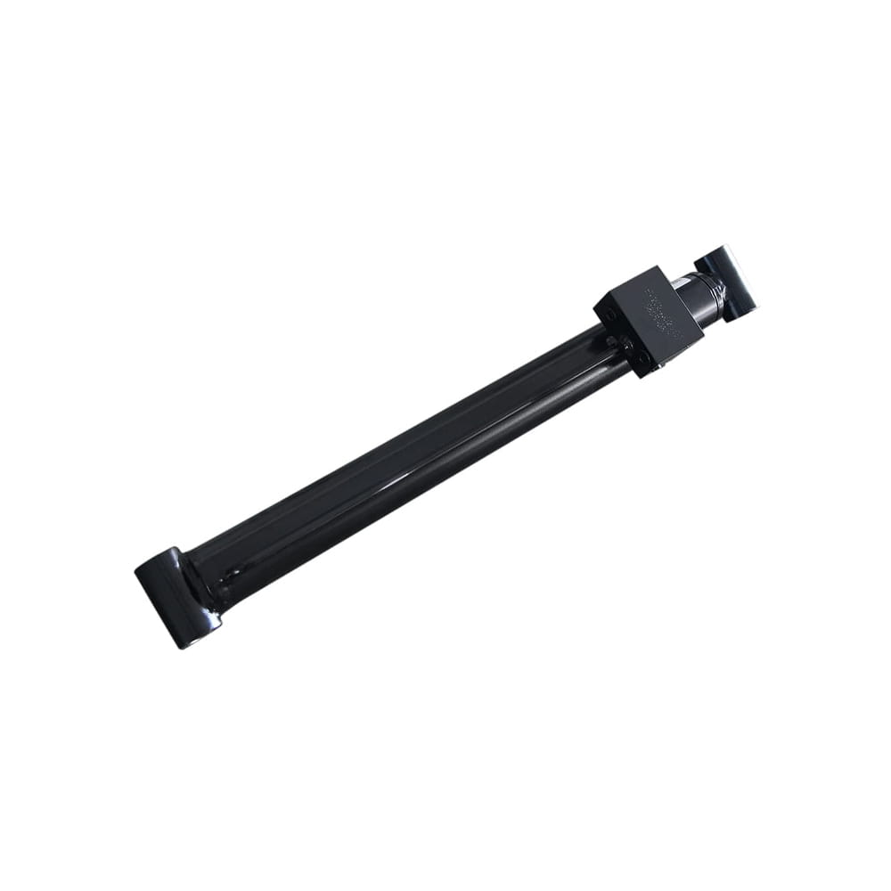 Scissor Lift Aerial Platform Hydraulic Lifting CylinderDetails single-acting lifting cylinders with damping holes for smooth ascent and descent, plus bore, rod and stroke ranges suited to scissor lift platform calculations.View Product →
Pipe jacking pushes the calculation to its limit. Main jacking cylinders drive pipe through the ground against soil resistance and wall friction, often at several hundred tonnes of thrust over a long stroke. Here the force budget is set by the ground conditions first and the hydraulics second, and the cylinder has to deliver that thrust repeatedly without buckling. You can see how these requirements differ across the range of hydraulic cylinders for piling machinery.
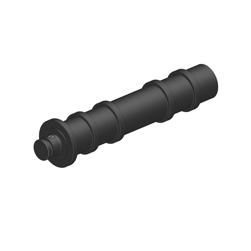 Pipe Jacking Machine Hydraulic Main Jacking CylinderCore power source for pipe jacking, delivering strong thrust, stable propulsion and precise extension control, with high-pressure resistance and sealing for harsh continuous operation.View Product →
Force in newtons equals pressure in megapascals multiplied by area in square millimetres. Everything else is conversion and correction.
Usually friction, back pressure, or a gauge reading taken downstream of a restriction. Check pressure at the cylinder port under load rather than at the pump.
For steady industrial loads, 1.25 to 1.5 is a sensible starting point. For shock loads, outdoor duty, or safety-critical holding functions, go higher and confirm with testing.
We have been building hydraulic cylinders in Zhejiang since 2004, and most of the force questions we answer come from engineers midway through a design rather than at the start. If you would like a second pair of eyes on the numbers, send us the load, the stroke, the pressure you expect, and how the cylinder is mounted — that is usually enough for us to tell you whether the bore you have chosen is comfortable or marginal. For more background on matching a cylinder to an application, our notes on key design considerations when selecting a hydraulic cylinder are a good place to continue.
Your email address will not be published. Required fields are marked *
Marvelous Design Meets Rigorous Manufacturing
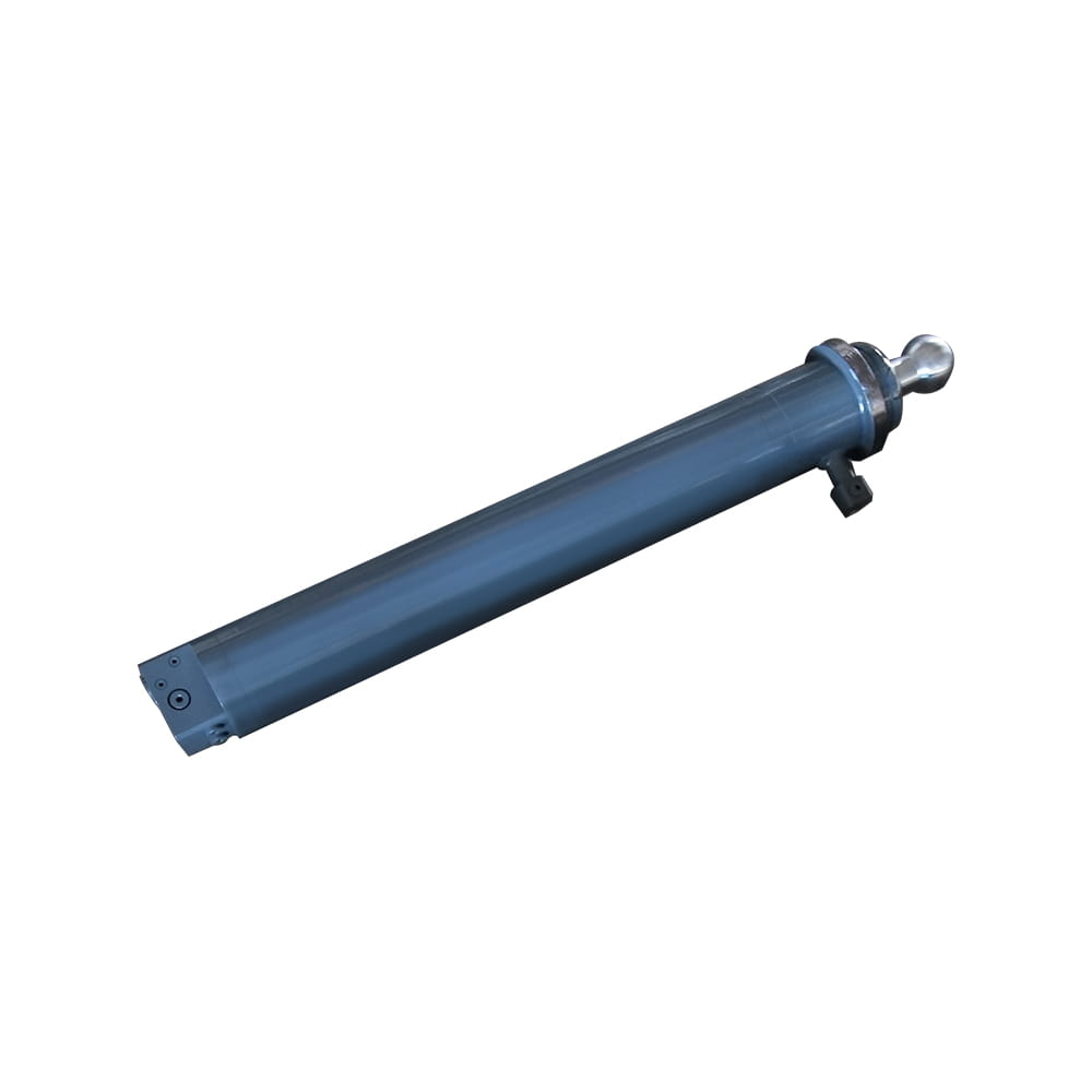 Scissor Lift Aerial Platform Hydraulic Outrigger Cylinder
Function: Firmly Supports the Vehicle: Ensures stability during operation. The ball-head foot automatically levels on slopes, while the integrated balance valve...
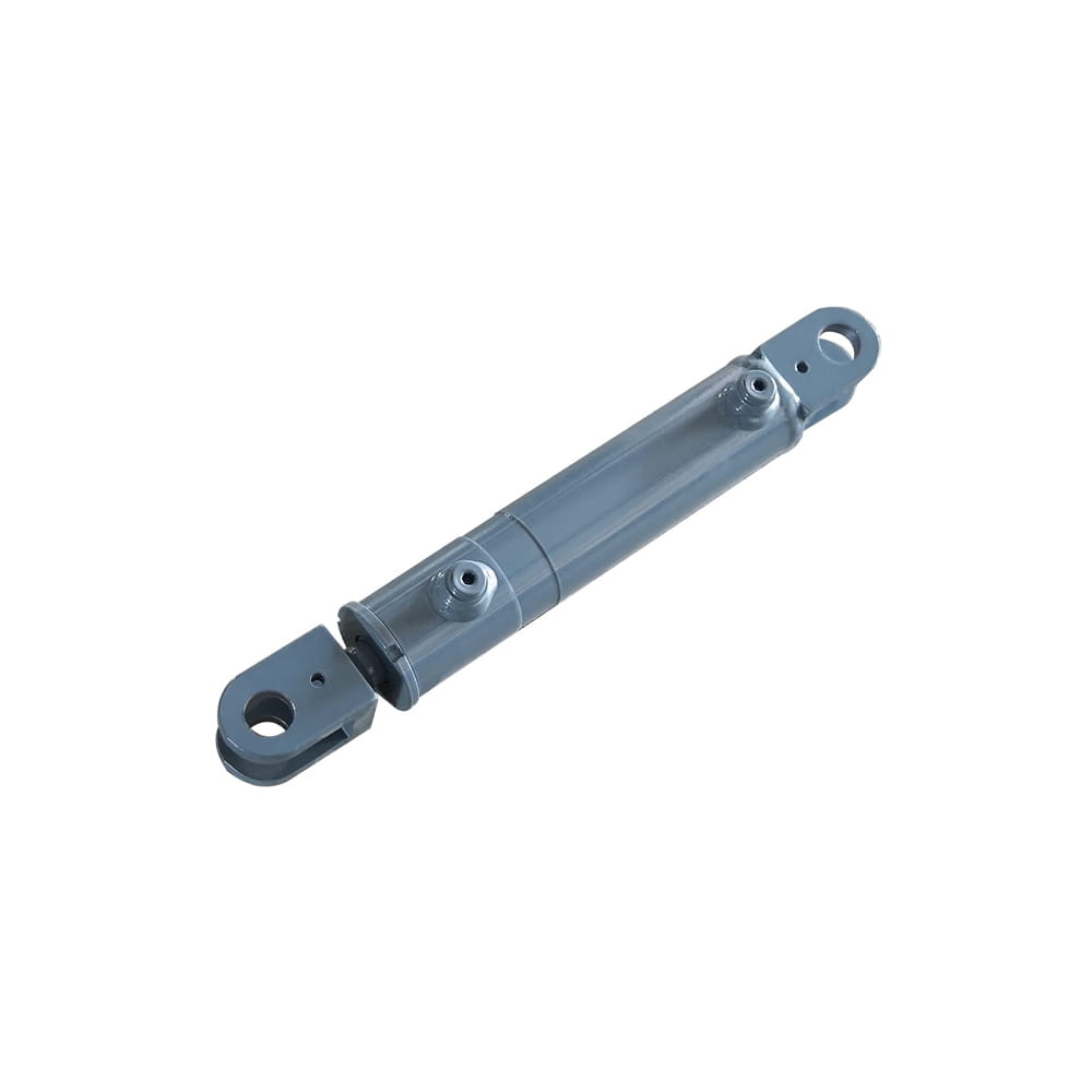 Scissor Lift Aerial Platform Hydraulic Steering Cylinder
Function: Connecting Chassis and Wheel Hub: Through hydraulic pressure, drives the piston rod to move, enabling precise wheel hub rotation. This ensures platfor...
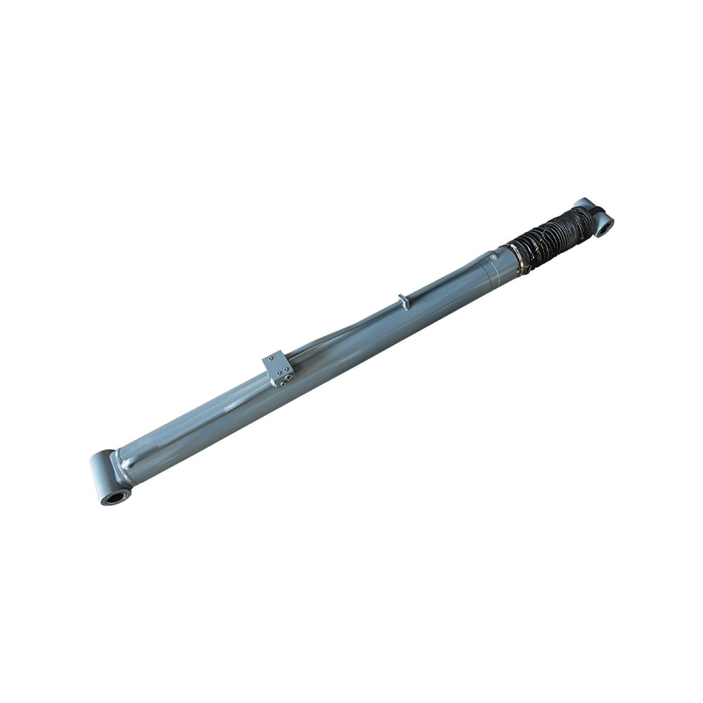 Boom Lift Aerial Platform Hydraulic Luffing Cylinder
Function: Adjust the angle of the telescopic arm to flexibly position the work platform at various heights and positions, meeting diverse aerial work requiremen...
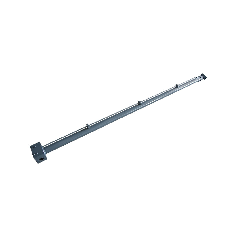 Boom Lift Aerial Platform Hydraulic Telescopic Cylinder
Function: Adjust the length of the arm to allow the aerial work platform to lift and move flexibly, ensuring range and height requirements.
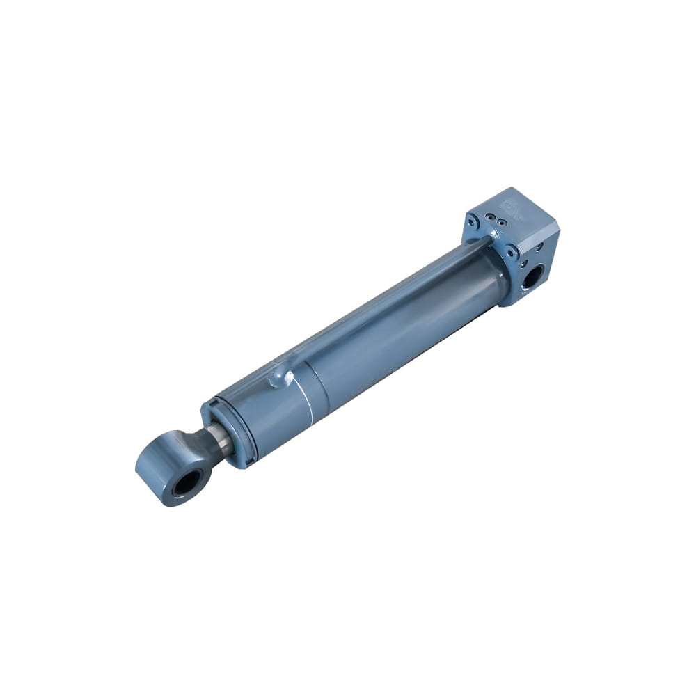 Boom Lift Aerial Platform Hydraulic Frame Leveling Cylinder
Function: Automatically adjust the chassis at the bottom of the platform to a level state, ensuring stable and wobble-free support in different terrains and wor...
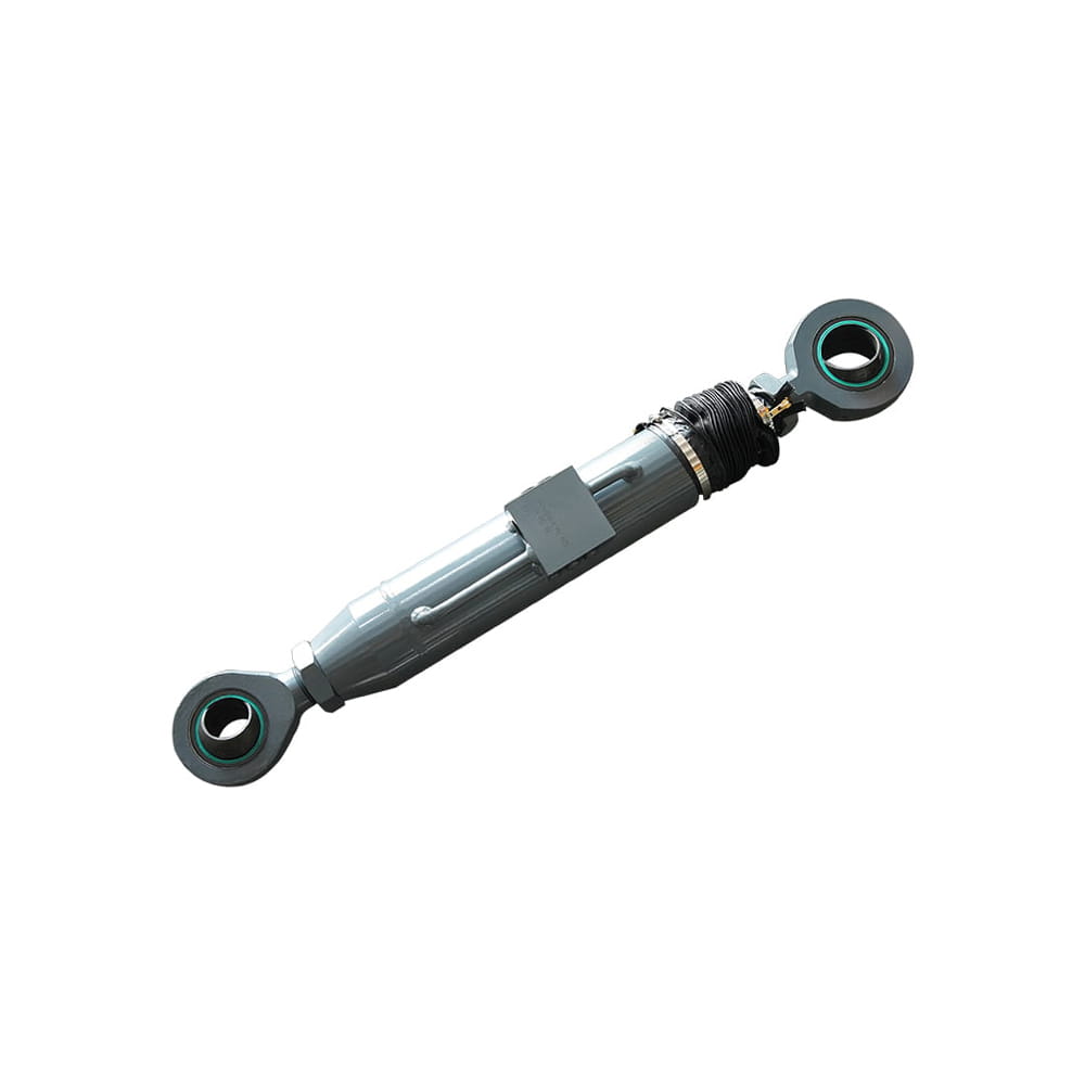 Boom Lift Aerial Platform Hydraulic Bridge Extension Cylinder
Function: An important design that enhances adaptability and working range. This function allows the platform to widen its chassis under specific conditions to ...
Copyright © by Zhejiang Huanfeng Machinery Co., Ltd. Rights Reserved.
