
 English
 中文简体
 русский
 Español
 Português
 عربى
Product Consultation
Your email address will not be published. Required fields are marked *
Piston area is one of those numbers that looks simple on paper but quietly decides how a hydraulic cylinder behaves in the field. Whether you are checking force, estimating speed, or comparing rod-side retraction against full-bore extension, the starting point is the same: get the area right. This guide walks through the area of piston formula, the net area on the rod side, and the practical details that matter when the numbers leave the page and enter a workshop.
Content
The area of a piston face is the area of a circle. If you know the radius, use A = πr². If you know the bore diameter, which is more common in cylinder work, use A = πd²/4. Here A is the area, d is the bore or piston diameter, r is half of that diameter, and π is approximately 3.1416. For a 100 mm bore, r = 50 mm, so A = π × 50² ≈ 7,854 mm². Using the diameter form gives the same result: π × 100² / 4 ≈ 7,854 mm². Keep the units consistent: mm with mm, cm with cm, inches with inches. A mixed-unit calculation is one of the fastest ways to produce a number that looks plausible but is wrong.
 Hydraulic Cylinder Piston in 45# and QT500-7Because piston geometry affects effective sealing area, this hydraulic cylinder accessory separates pressure media and is available in 45# and QT500-7.View Product →
Piston geometry matters as much as the arithmetic. A piston that is not concentric, or a bore that is worn or scored, can change the effective sealing area in service even when the nominal formula is correct. That is why the formula is a starting point, not a substitute for inspection.
In most hydraulic cylinder documentation, the bore is given as a diameter, not a radius. That is convenient because the diameter form avoids one conversion step. The steps are straightforward:
With a 63 mm bore, A = π × 63² / 4 ≈ 3,117 mm². With a 3.00 in bore, A = π × 3.00² / 4 ≈ 7.07 in². The arithmetic is easy; the discipline is in keeping nominal bore, actual bore, and rod diameter separate. A cylinder may be listed as 100 mm bore, but the measured bore can sit slightly above or below that value depending on tolerance and wear. For force estimates, use the nominal figure; for fault finding, measure the real bore.
In a double-acting cylinder, the piston does not push against the full piston area in both directions. On the rod side, the rod takes up part of the piston face. The effective area is the annular area: A_net = π/4 (D² - d²), where D is the bore diameter and d is the rod diameter. This is the area that the hydraulic fluid actually acts on during retraction. Ignoring the rod area is one of the most common errors in force calculations, especially on long-stroke cylinders where the rod is large relative to the bore.
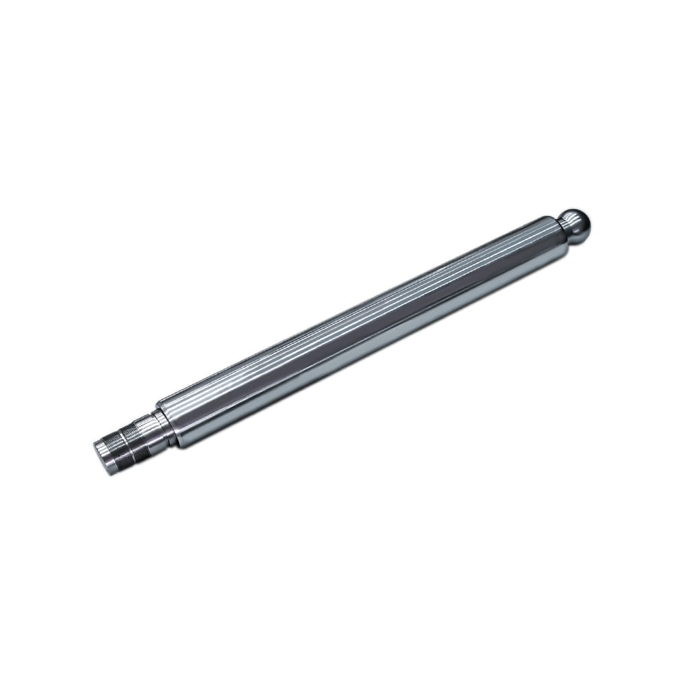 Chrome-Plated Hydraulic Piston Rod 20–220 mmWith 20–220 mm diameter, up to 8000 mm length, and chrome plating, this piston rod is relevant when rod area affects net force calculations.View Product →
The rod diameter is not a minor detail. It sets the net area, and it also affects column strength and seal friction. A rod that is undersized for the load may deflect, while a rod that is oversized reduces retraction force because it removes more area from the piston face. The table below shows the difference for common bore and rod combinations.
| Bore D (mm) | Rod d (mm) | Full piston area (mm²) | Rod area (mm²) | Net annular area (mm²) |
|---|---|---|---|---|
| 80 | 45 | 5,026.55 | 1,590.43 | 3,436.12 |
| 100 | 56 | 7,853.98 | 2,463.01 | 5,390.97 |
| 125 | 70 | 12,271.85 | 3,848.45 | 8,423.40 |
Once the area is known, force follows directly: F = p × A. With p in N/mm² (MPa) and A in mm², force comes out in newtons. For a 100 mm bore at 16 MPa, the extension force is about 7,854 mm² × 16 N/mm² ≈ 125,664 N, or 125.7 kN. On the rod side, using the net area from the table, the retraction force is about 5,391 mm² × 16 N/mm² ≈ 86,256 N, or 86.3 kN. That difference is not a rounding error; it is the rod doing its job.
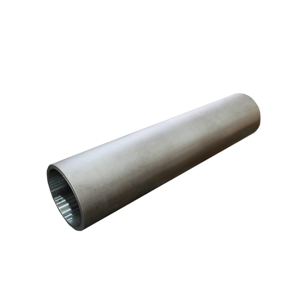 Cylinder Tube for Hydraulic Cylinders, Φ40–Φ320 mmWith honed or rolled inner surfaces and materials including 20#, 45#, Q345B, and 27SiMn, this tube supports roundness and sealing in bore-based force calculations.View Product →
The bore is created by the cylinder tube, so tube quality and roundness influence how closely the real cylinder follows the calculated area. A tube that is out of round or worn can change the effective clearance and sealing behaviour, even if the nominal diameter on the drawing has not changed.
Speed uses the same area in reverse: v = Q / A, where Q is flow and A is the effective area. If flow is in mm³/min and area in mm², speed is in mm/min. Keep an eye on extension versus retraction; the rod-side area is smaller, so retraction is usually faster for the same flow. That is one reason a cylinder can feel different in each direction even when the pressure setting is unchanged. The formula gives theoretical force. Real force is lower because of seal friction, pressure drop, and back pressure. For initial sizing, the theoretical figure is still the right starting point; for detailed design, test or account for those losses.
For a broader design checklist, our article on key design considerations when selecting a hydraulic cylinder for a specific application walks through bore, stroke, mounting, and load conditions.
At Zhejiang Huanfeng Machinery, we have been building hydraulic cylinders since 2004, and the area formula comes up in almost every conversation about force, speed, or cylinder sizing. The math is stable, but the inputs deserve respect. A bore measured with a worn caliper, a rod diameter taken from an old drawing, or a pressure figure quoted without units can send an otherwise sound calculation off course. We prefer to confirm the basics first: bore, rod, stroke, pressure, flow, and mounting. Then the formula does what it should.
We see the same pattern across crane, aerial work platform, tow truck, and piling machinery cylinders: the rod-side area is the one that gets overlooked. Seal friction does not change the geometric area, but it changes the force you can use. If you are chasing a force shortfall, check the seals and the rod surface as well as the arithmetic. If you keep the formula close and the units honest, piston area stops being a classroom exercise and becomes a practical troubleshooting tool. Start with the full bore area, subtract the rod area when the cylinder retracts, and remember that the real machine always has a little more going on than the ideal equation.
Your email address will not be published. Required fields are marked *
Marvelous Design Meets Rigorous Manufacturing
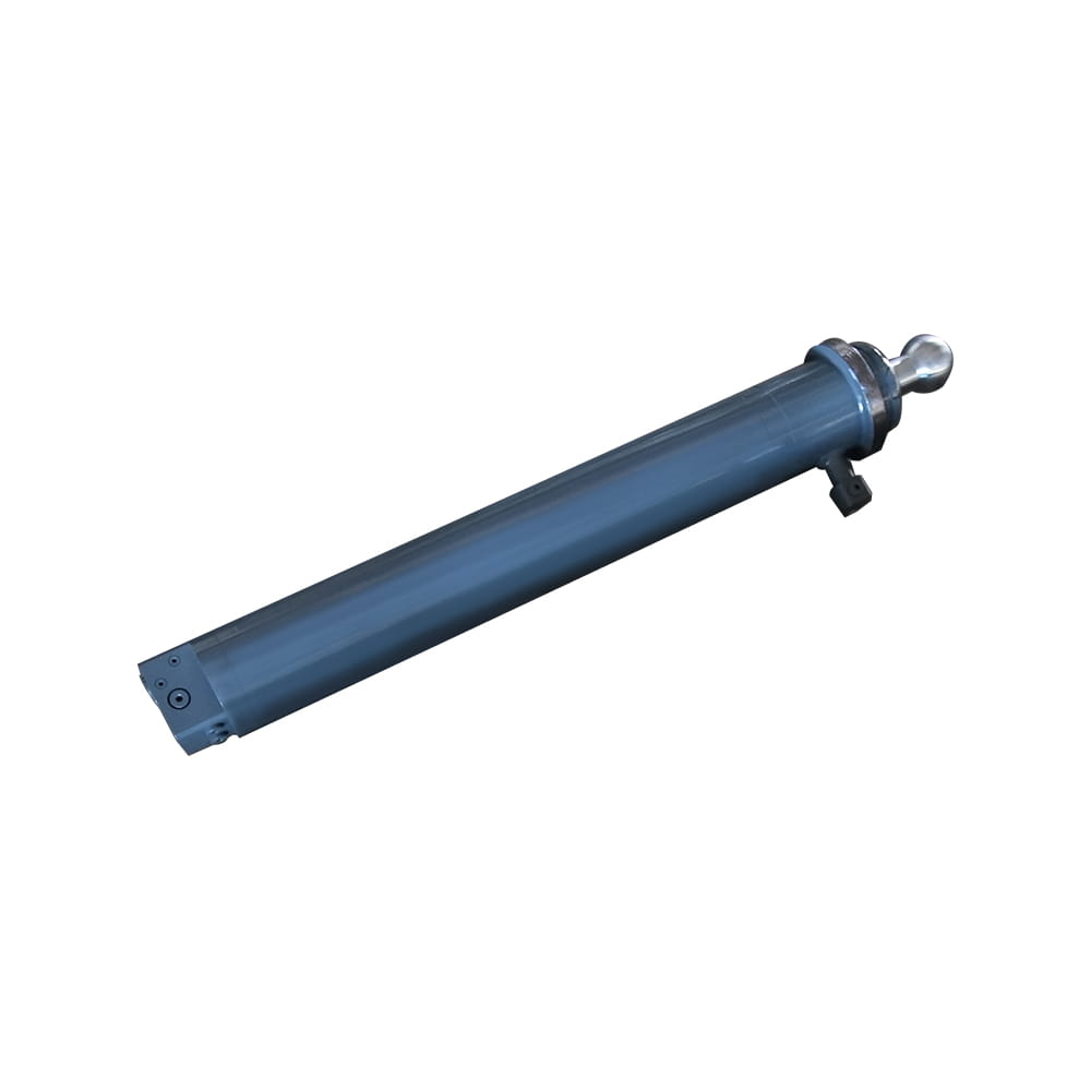 Scissor Lift Aerial Platform Hydraulic Outrigger Cylinder
Function: Firmly Supports the Vehicle: Ensures stability during operation. The ball-head foot automatically levels on slopes, while the integrated balance valve...
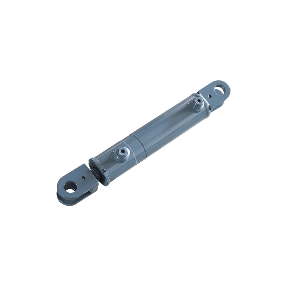 Scissor Lift Aerial Platform Hydraulic Steering Cylinder
Function: Connecting Chassis and Wheel Hub: Through hydraulic pressure, drives the piston rod to move, enabling precise wheel hub rotation. This ensures platfor...
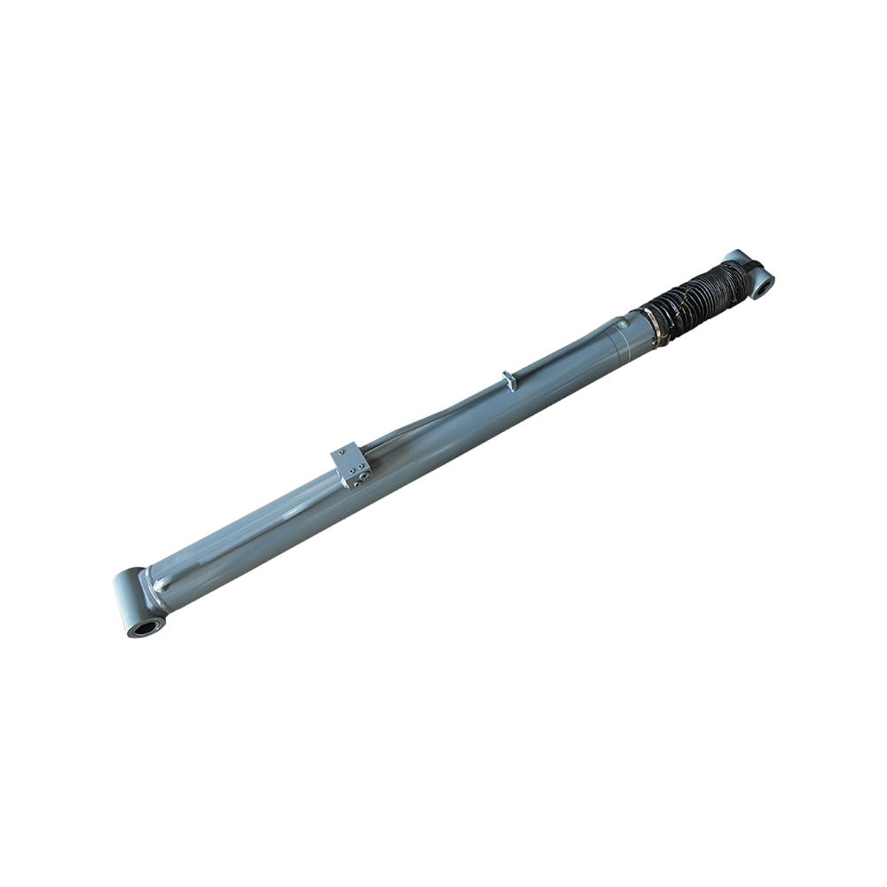 Boom Lift Aerial Platform Hydraulic Luffing Cylinder
Function: Adjust the angle of the telescopic arm to flexibly position the work platform at various heights and positions, meeting diverse aerial work requiremen...
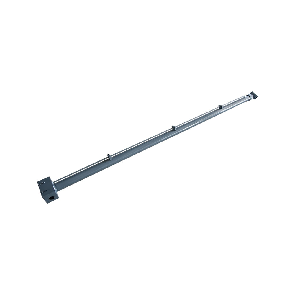 Boom Lift Aerial Platform Hydraulic Telescopic Cylinder
Function: Adjust the length of the arm to allow the aerial work platform to lift and move flexibly, ensuring range and height requirements.
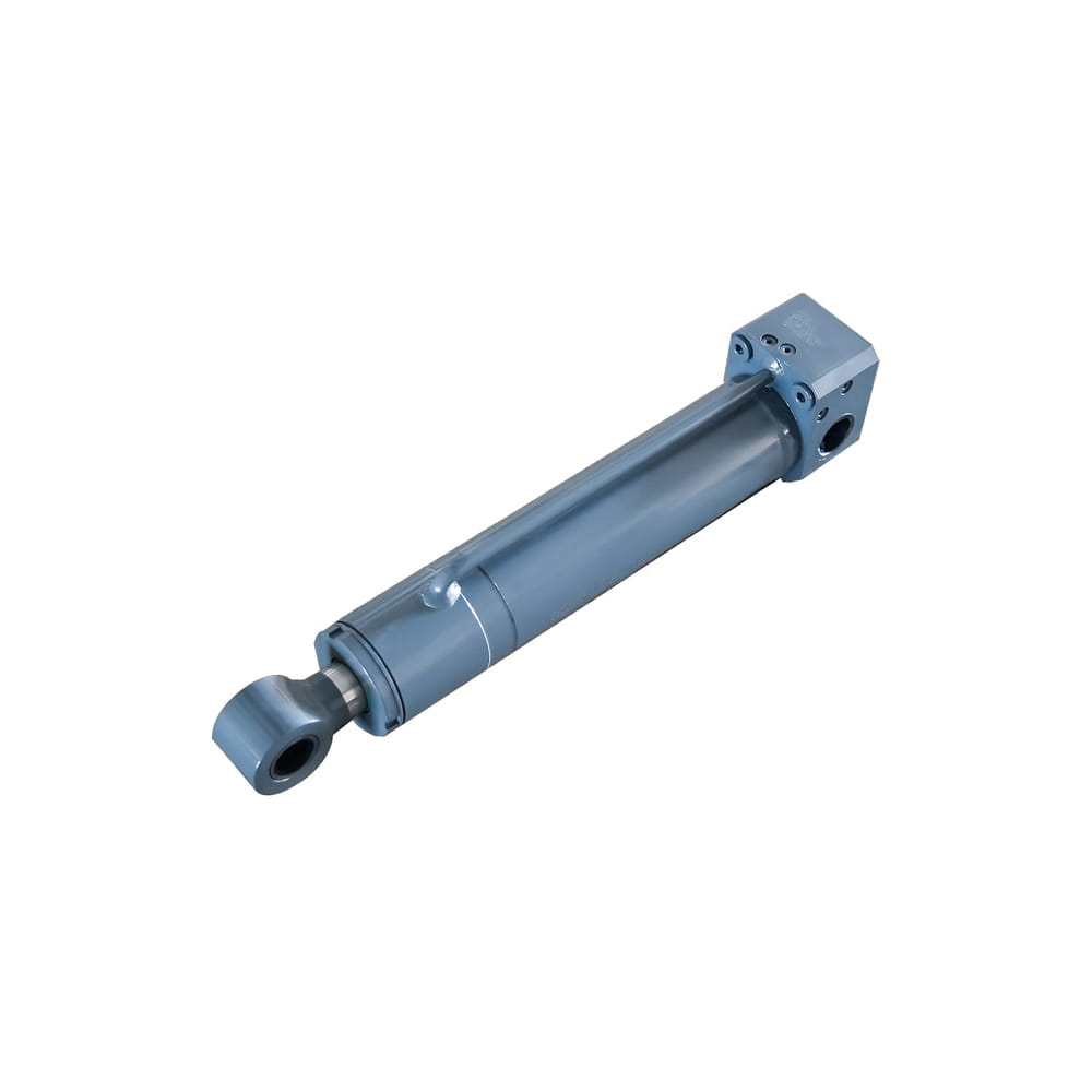 Boom Lift Aerial Platform Hydraulic Frame Leveling Cylinder
Function: Automatically adjust the chassis at the bottom of the platform to a level state, ensuring stable and wobble-free support in different terrains and wor...
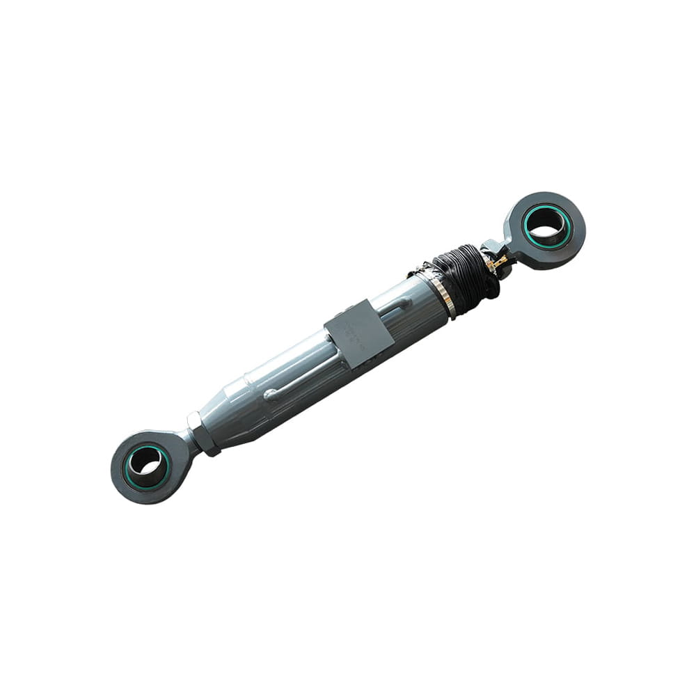 Boom Lift Aerial Platform Hydraulic Bridge Extension Cylinder
Function: An important design that enhances adaptability and working range. This function allows the platform to widen its chassis under specific conditions to ...
Copyright © by Zhejiang Huanfeng Machinery Co., Ltd. Rights Reserved.
