
 English
 中文简体
中文简体 русский
 Español
 Português
 عربى
عربىProduct Consultation
Your email address will not be published. Required fields are marked *
Content
A successful hydraulic horizontal cylinder installation is defined by one overriding goal: ensuring the cylinder rod extends and retracts with zero side load throughout its entire stroke. Every step in the process—from foundation preparation to final torque tightening—serves this single principle. When a horizontally mounted cylinder deviates from perfect alignment by even a fraction of a degree, the rod becomes a lever arm pressing the piston against the cylinder bore wall. This metal-to-metal contact destroys the piston bearing, damages the rod seal, and often scores the barrel itself. The direct consequence is not a gradual performance decline but a sudden and catastrophic failure, typically occurring at the rod gland where high-pressure fluid escapes or the rod bends under the unintended bending moment.
Therefore, the installation is not merely a mechanical lift and bolt-down task; it is a precision alignment exercise. The cylinder must be treated as a sensitive, self-centering linear bearing whose mounting surfaces dictate its service life. A correctly installed horizontal cylinder will deliver its full design life, often exceeding 10,000 operational hours even under heavy cyclic loading, while a misaligned unit can destroy its seals and bearings in under 50 cycles.
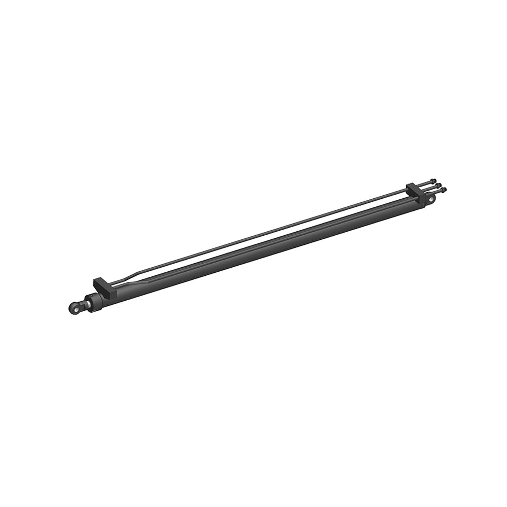
Before any lifting or positioning begins, a thorough inspection of the cylinder and its mating structure is non-negotiable. Cylinders often sit in storage for extended periods, accumulating internal condensation or suffering port contamination. Verify that all threaded ports are fitted with clean, undamaged plugs and that the rod is fully retracted—this protects the chrome surface during handling. Manually cycle the cylinder, if possible, using a small hand pump to confirm smooth movement and absence of internal blockages. Document the serial number and check that the mounting dimensions stamped on the nameplate match the engineering drawing for the application.
The foundation or machine frame must present a flat, rigid, and clean mounting plane. For foot-mounted horizontal cylinders, measure the flatness of the mounting pads using a precision machinist's level or a laser alignment system. A tolerance of 0.1mm per meter is a common maximum deviation. Any gap between the cylinder foot and the pad becomes a bending stress when the mounting bolts are tightened. Do not use shims arbitrarily; if shimming is required to correct height, full-surface steel shims must be ground flat and cover the entire footprint of the cylinder foot to prevent the introduction of an angular twist into the body. Wipe down the mounting pads to remove paint overspray, weld spatter, or rust scale, as these compress over time and cause the hold-down bolts to lose preload.
Alignment is the procedural heart of the installation. For a horizontal cylinder mounted with a clevis or spherical bearing at each end, the objective is to achieve perfect coaxiality between the cylinder's theoretical centerline and the load's direction of travel. The most effective field method involves mounting the cylinder's fixed end, typically the cap end, first. Connect the rod end pin to the driven structure loosely, so the pin is seated but the structure can still articulate. With the hydraulic lines still disconnected, manually pull the rod out to its mid-stroke position.
At this position, measure the vertical and horizontal offset between the cylinder rod centerline and the fixed pivot point axis. A dial indicator mounted on the machine frame and run along a precision ground bar inserted through the rod eye is the traditional, reliable technique. Tolerances here are tight: aim for ≤ 0.15mm total indicated runout across the entire exposed rod length. If the measurements exceed this, the cap end mount must be repositioned or the structure's pivot bearing adjusted. Never use the cylinder rod itself as a come-along to force a misaligned structure into position; this permanently springs the rod or damages the piston-to-rod thread interface. The alignment is acceptable only when the pin slides through the rod eye and the mating lug with light finger pressure at any point in the stroke.
Understanding the cylinder's mounting style is fundamental, as the bolt torque strategy differs sharply between flange, foot, and trunnion designs, and the consequences of errors manifest differently.
When bolting down a foot or rectangular flange cylinder, follow a controlled torque sequence, starting from the inner bolts on the cap end and working outward in a diagonal pattern. This drives the cylinder body flat against the mounting surface without arching. Refer to the manufacturer's manual for the specific bolt class, but as a practical reference, a typical 12.9 grade M20 bolt on a heavy industrial cylinder requires a torque in the range of 570 Nm. Under-torquing leads to fretting between the foot and pad under pressure cycling, eventually shearing the bolts. After the first 50 operating hours, re-torque all accessible bolts to compensate for surface embedment relaxation.
Trunnion-mounted cylinders require a completely different focus. The trunnion pins must be perfectly perpendicular to the cylinder's axial centerline, and the bearing blocks must be aligned so the cylinder is not axially pinched. These cylinders must be free to swing slightly as the rod extends and contracts. A critical installation error is rigidly constraining a trunnion cylinder's body. The bearing housings should allow a small axial float, typically 0.25mm to 0.5mm, on one side to accommodate thermal expansion of the cylinder barrel and prevent the body from being placed in tension, which distorts the bore. Verify this float exists after bolting down the pillow blocks by using a feeler gauge between the bearing face and the trunnion shoulder.
Connecting the hydraulic lines is where the system's lifeblood is protected or permanently contaminated. Do not remove shipping plugs from the cylinder ports until the moment the hose or tube fitting is ready for immediate attachment. Use absolute cleanliness discipline; wipe the male threads and the female port with a lint-free cloth and an approved solvent. Apply thread sealant only to the male fitting threads, keeping it two threads back from the end to prevent any compound from extruding into the hydraulic stream. A single strand of PTFE tape or a drop of liquid sealant that enters the cylinder can lodge in a cushion valve or the piston seal, causing intermittent lock-up.
After the lines are connected, the cylinder must be fully bled before it is put into production. An air-filled cylinder is dangerous, exhibiting spongy, unpredictable motion and suffering from diesel-effect ignition of oil mist that burns seals. The correct bleeding method for a double-acting horizontal cylinder is to crack open the rod-end pipe fitting slightly—just enough to weep fluid—and jog the pump to move the piston slowly toward the cap end. Oil mixed with fine air bubbles will escape. Tighten the fitting, then repeat the process by cracking the cap-end fitting while retracting the rod. This sequence pushes the entrapped air volume out of the relatively larger cap-end chamber first, making the final rod-end bleed more effective. Run the cylinder through at least five full, slow-speed cycles to collect any remaining free air in the reservoir before moving to full pressure operation.
Commissioning through a structured test validates the entire installation sequence. Begin with a low-pressure function test, typically at 10% to 15% of system operating pressure, and observe the cylinder's movement through its full stroke. Listen for rhythmic scraping or stick-slip chatter, which indicates binding or an internally damaged rod. Check all port connections with a dry piece of cardboard held near the fitting—a jet of high-pressure oil is often invisible and can cause injection injuries.
Gradually ramp to full working pressure while monitoring the rod gland for external leakage. A negligible film of oil is part of normal seal lubrication, but drop formation indicates the rod seal was damaged during installation or a misaligned rod is deflecting the lip. Next, apply the full intended working load and hold the cylinder at mid-stroke in a pressurized stall condition for five minutes. Measure any drift using a dial indicator on the rod end. Excessive drift beyond the manufacturer's specified limit—commonly less than 0.5mm per minute for a piston-sealed cylinder—reveals internal bypass across the piston seal, a crossed seal, or a contaminated valve holding the load. Finally, document the pressure gauge readings, drift measurements, and ambient temperature on the commissioning report. This baseline data is invaluable for diagnosing future performance degradation long after the installation crew has left the site.
Your email address will not be published. Required fields are marked *
Marvelous Design Meets Rigorous Manufacturing
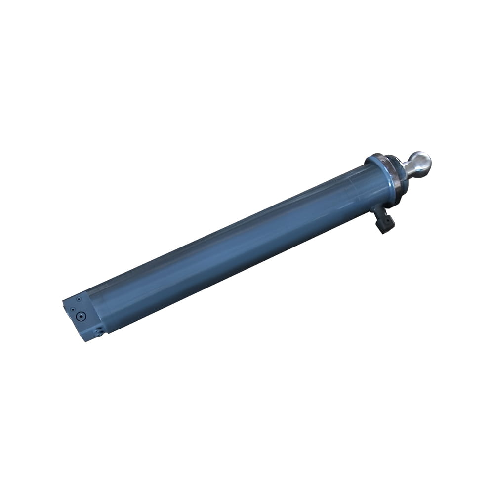 Scissor Lift Aerial Platform Hydraulic Outrigger Cylinder
Function: Firmly Supports the Vehicle: Ensures stability during operation. The ball-head foot automatically levels on slopes, while the integrated balance valve...
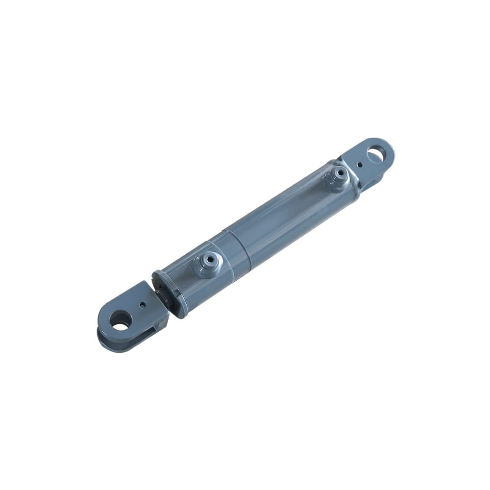 Scissor Lift Aerial Platform Hydraulic Steering Cylinder
Function: Connecting Chassis and Wheel Hub: Through hydraulic pressure, drives the piston rod to move, enabling precise wheel hub rotation. This ensures platfor...
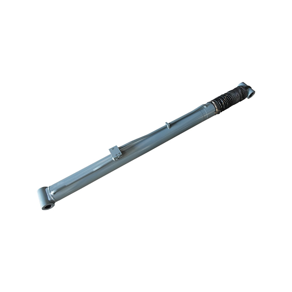 Boom Lift Aerial Platform Hydraulic Luffing Cylinder
Function: Adjust the angle of the telescopic arm to flexibly position the work platform at various heights and positions, meeting diverse aerial work requiremen...
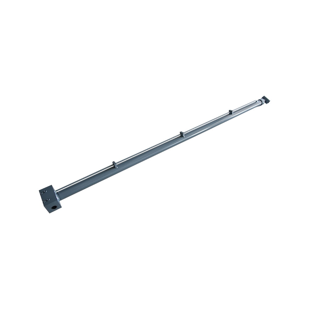 Boom Lift Aerial Platform Hydraulic Telescopic Cylinder
Function: Adjust the length of the arm to allow the aerial work platform to lift and move flexibly, ensuring range and height requirements.
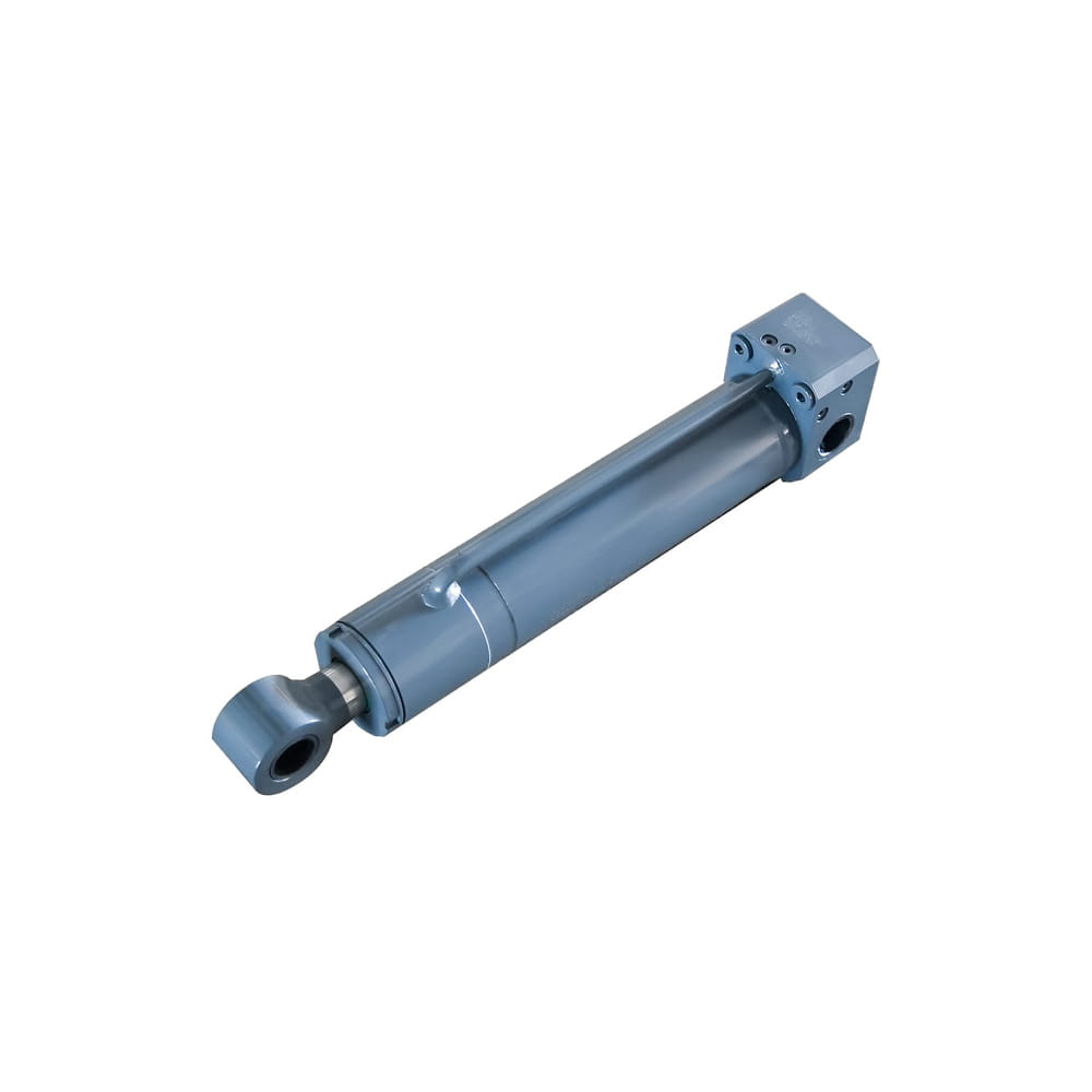 Boom Lift Aerial Platform Hydraulic Frame Leveling Cylinder
Function: Automatically adjust the chassis at the bottom of the platform to a level state, ensuring stable and wobble-free support in different terrains and wor...
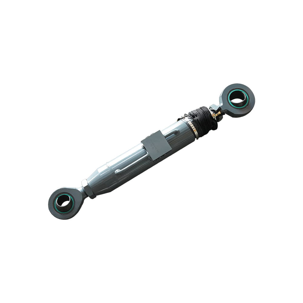 Boom Lift Aerial Platform Hydraulic Bridge Extension Cylinder
Function: An important design that enhances adaptability and working range. This function allows the platform to widen its chassis under specific conditions to ...
Copyright © by Zhejiang Huanfeng Machinery Co., Ltd. Rights Reserved.
