 English
 中文简体
中文简体 русский
 Español
 Português
 عربى
عربىProduct Consultation
Your email address will not be published. Required fields are marked *
Content
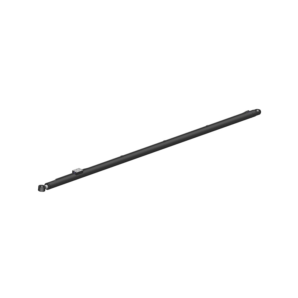
A side-loader crane hydraulic skid cylinder is functionally distinct from a standard hydraulic cylinder because it operates as both an actuator and a structural guide. Its primary job is to extend and retract the intermediate boom section or the skid carriage that carries the lifting fork assembly, but while extended, the cylinder body and rod must resist the bending moment imposed by the offset load—a load that can produce a side force equivalent to 30% to 60% of the rated lift capacity depending on the boom extension length and the load center distance. This combined axial and bending load condition is what distinguishes a skid cylinder from a purely axial hydraulic cylinder on a conventional crane. The cylinder's rod diameter, rod support bearing spacing, and the internal piston guide ring design are all engineered to maintain a straight-line motion under load without allowing the rod to buckle or the piston to cock inside the barrel, either of which would immediately score the cylinder bore and initiate a seal failure cascade. A skid cylinder on a typical 10-ton side-loader operates at working pressures between 180 and 250 bar, with test pressures reaching 375 bar, and the cylinder body is typically manufactured from honed cold-drawn seamless steel tube conforming to DIN 2391 or ASTM A519 with a bore surface finish of 0.2 to 0.4 microns Ra.
The single most critical design parameter for a side-loader crane hydraulic skid cylinder is the rod diameter relative to the stroke length. When the cylinder is fully extended, the rod is a column under compression, and the slenderness ratio—the effective column length divided by the radius of gyration of the rod cross-section—must remain below the Euler buckling threshold for the applied load. For a skid cylinder with a stroke of 1.5 meters and a rod diameter of 60 millimeters, the slenderness ratio is approximately 100:1 under pinned-end conditions. If the rod support bearing at the rod eye end provides effective lateral restraint, the effective length is reduced and the buckling capacity increases by a factor of up to four compared to an unguided rod. This is why the skid cylinder rod is always supported at its outer end by a slide block or roller carriage that runs on the boom structure's internal guide rails—the rod end is not free to move laterally, and this guide system is a load-bearing component of the cylinder assembly, not merely an alignment convenience. When the guide block wears beyond its specified clearance—typically 0.5 to 1.0 millimeters maximum—the rod end gains lateral freedom, the effective column length increases, and the cylinder operates outside its designed buckling envelope.
The piston rod on a skid cylinder is chrome-plated to a minimum thickness of 20 microns for standard service and 30 to 50 microns for marine or corrosive environments, applied over a nickel undercoat that provides the actual corrosion barrier. The chrome layer is not corrosion-resistant—it is micro-cracked and porous—but the nickel undercoat seals the steel substrate. When surface rust spots appear on a skid cylinder rod, it indicates that the chrome layer has worn through and the nickel undercoat has been breached, exposing the steel. At this point, the rod is in the early stages of pitting failure, and every extension-retraction cycle draws the pitted surface through the rod seal, abrading the seal lip and introducing contamination into the hydraulic fluid.
Inside a side-loader crane hydraulic skid cylinder, the piston does not contact the barrel wall directly. It rides on phenolic or glass-filled PTFE guide rings that are installed in grooves machined into the piston OD, typically two guide rings spaced 30 to 50 millimeters apart with the piston seal positioned between them. These guide rings absorb the side load component of the skid cylinder's combined loading and prevent metal-to-metal contact between the piston and the barrel. The rod gland at the cylinder head end contains a similar guide bushing—often a bronze-backed PTFE composite—that supports the rod against side loading and maintains concentricity with the rod seal. The clearance between the guide rings and the barrel bore, and between the rod bushing and the rod, is specified at 0.10 to 0.25 millimeters diametral for a cylinder of 80 to 120 millimeters bore. When this clearance doubles due to guide ring wear, the piston seal begins to extrude into the gap under pressure, and the rod seal is subjected to non-concentric loading that accelerates its wear. The guide ring replacement interval for a skid cylinder in heavy-duty container handling operation is typically 3,000 to 5,000 operating hours, at which point the cylinder should be disassembled and the guide rings measured and replaced regardless of whether the seals are visibly leaking.
The rod seal on a skid cylinder is not a single component. It is a stacked arrangement of at least three functional elements: a primary polyurethane U-cup seal that holds system pressure, a secondary buffer seal that protects the primary seal from pressure spikes and provides a backup sealing lip, and an external wiper seal that scrapes contamination from the rod surface before it reaches the sealing elements. In cylinders operating in environments with high particulate contamination—port areas with coal dust, cement, or metal shavings—a fourth element, a metal scraper ring, may be installed ahead of the wiper to mechanically remove bonded debris that the elastomeric wiper cannot dislodge. The seal material selection depends on the hydraulic fluid type and operating temperature: standard polyurethane seals are rated for -30 to +100 degrees Celsius; for high-temperature applications above 100 degrees, fluorocarbon seals are specified. The single most common seal failure mode in skid cylinders is the wiper seal degrading and allowing contamination to reach the primary U-cup, which then acts as a lapping compound between the seal lip and the chrome rod surface, wearing a groove into both.
The piston seal, located on the piston inside the cylinder barrel, separates the full-bore side of the cylinder from the annulus side. It is typically a PTFE-based step-cut seal with an elastomeric energizer ring that provides the radial contact force, or a glass-filled PTFE slipper seal for higher-pressure applications. When the piston seal wears, hydraulic fluid bypasses internally from the high-pressure side to the low-pressure side of the piston, and the symptom is cylinder drift under load—the skid carriage slowly retracts even though the control valve is in the neutral position. This internal leakage does not produce an external fluid leak, and it cannot be diagnosed from a visual inspection. The test is to pressurize the cylinder with the rod fully extended and measure the rod retraction rate over a timed interval; a drift rate exceeding 5 millimeters per minute under rated load typically indicates a piston seal that requires replacement.
The skid cylinder on a side-loader crane operates horizontally, and this orientation makes it more vulnerable to certain contamination-related failure modes than a vertically mounted cylinder. In a vertical cylinder, gravity helps settle particulate contamination to the bottom of the barrel, away from the piston seal. In a horizontal skid cylinder, the contamination remains suspended along the full length of the barrel bore, and every stroke drags the particles across the entire seal contact surface. The rod, when extended, is exposed to ambient dust and moisture, and every retraction cycle pulls whatever has settled on the rod surface into the wiper seal. The hydraulic system filtration should maintain fluid cleanliness to ISO 4406 18/16/13 or better for a skid cylinder operating in a port or industrial environment, with the return-line filter capturing particles down to 10 microns absolute. A filter bypass indicator that is ignored or a filter element that is not changed at the specified interval puts the skid cylinder seals into direct contact with abrasive particles that reduce seal life by 50% to 70% relative to a cylinder operating with clean fluid.
The piston rod on a side-loader crane hydraulic skid cylinder must maintain a straightness tolerance that is often specified but rarely field-verified after the cylinder has been in service. The standard straightness tolerance for a new skid cylinder rod is 0.2 millimeters per meter of rod length, measured as total indicator reading at the rod midpoint with the rod supported at both ends. A rod that has been bent—typically from a side impact to the skid carriage or from operating the crane with the boom overloaded and the skid cylinder partially extended—will exceed this tolerance. A bent rod imposes a cyclic side load on the rod bushing and seal with every stroke, producing a characteristic wear pattern: the rod bushing wears into an oval shape, and the rod seal develops a leak that appears only at one specific rod extension position—the position where the bent section passes through the seal. Checking rod straightness with a dial indicator and V-blocks is a diagnostic step that should be performed whenever a skid cylinder exhibits unexplained seal failure shortly after replacement, because a bent rod will destroy a new seal set within weeks of installation.
The skid cylinder is mounted between the crane's main boom structure and the sliding skid carriage through pinned clevis mounts at both ends. If these two mounting points are not aligned on the same axis within the specified tolerance, the cylinder is subjected to a permanent side load that acts on the rod bearing and piston guides even when the cylinder is not under working load. The alignment tolerance for a skid cylinder installation is typically ±0.5 millimeters coaxiality between the barrel-end and rod-end mounting pins over the full stroke length. Misalignment can be introduced during initial assembly, or it can develop over time as the crane structure fatigues, as weldments distort, or as the skid carriage guide rails wear unevenly. The diagnostic indicator of mounting misalignment is a cylinder that leaks from the rod seal or shows uneven rod bushing wear despite having a straight rod, clean fluid, and correctly specified seals. The corrective action is to disconnect the rod end, measure the alignment between the pin bores with the cylinder at mid-stroke using a tight wire or laser alignment tool, and shim or machine the mounting brackets to bring the alignment within specification.
Rebuilding a side-loader crane hydraulic skid cylinder follows a specific sequence that prevents damage to the newly installed components. Before disassembly begins, the cylinder must be fully retracted and the hydraulic lines capped to prevent fluid loss and contamination entry. The rod gland is unscrewed using a pin spanner or a fabricated wrench that engages the gland's spanner holes—never a pipe wrench, which deforms the gland and creates a leak path. The rod and piston assembly is withdrawn from the barrel using a controlled overhead lift, and the piston is immediately supported on V-blocks to prevent the rod weight from bending the rod at the piston thread junction. The piston retaining nut is removed—this is often secured with Loctite and requires heating to 150 degrees Celsius to release—and the piston and gland are slid off the rod. The barrel bore is inspected with a borescope for scoring, and any scratch deeper than 0.5 millimeters that can be felt with a fingernail requires the barrel to be honed or replaced. The new seals are installed using purpose-made installation sleeves that prevent the seal lips from being cut by the sharp edges of the rod threads and the barrel port openings during reassembly. The gland retaining threads and the piston nut threads are cleaned and coated with anti-seize compound, and the gland is torqued to the manufacturer's specification—typically 200 to 400 Newton-meters for a cylinder of 100 millimeters bore. After assembly, the cylinder is cycled five times at low pressure to allow the seals to seat, then tested at full system pressure while observing for external leakage and rod drift.
| Operating Hours | Inspection Action | Service Action |
|---|---|---|
| Every 250 hours | Visual inspection of rod for pitting, scoring, chrome damage | Clean rod, replace wiper seal if damaged |
| Every 1,000 hours | Check guide block clearance, rod straightness, mounting alignment | Adjust or replace guide blocks, re-align if necessary |
| 3,000–5,000 hours | Measure internal drift rate, inspect barrel bore with borescope | Replace all seals and guide rings, hone barrel if scored |
| 10,000 hours or major leak | Full disassembly, dimensional check of rod and barrel | Replace rod if pitted or bent beyond tolerance |
When a skid carriage drifts under load, the cause may be internal cylinder leakage, or it may be the directional control valve that supplies the cylinder. The two conditions produce identical symptoms—the carriage moves when it should remain stationary—but require completely different corrective actions. The definitive diagnostic procedure is the cylinder isolation test: with the cylinder under load, the hydraulic lines at the cylinder ports are disconnected and capped with JIC or ORFS blanking plugs rated for the system pressure. If the carriage drift stops immediately when the lines are capped, the leakage is in the control valve, because the capped cylinder is holding pressure. If the drift continues with the lines capped, the leakage is internal to the cylinder across the piston seal. Performing this test requires strict safety precautions—the load must be supported independently before disconnecting any hydraulic line, and the blanking plugs must be rated for the full system pressure including pressure spikes. Substituting a lower-rated plug or a makeshift plug can result in a catastrophic high-pressure fluid release.
The service life of a side-loader crane hydraulic skid cylinder is directly proportional to the consistency of three preventive maintenance actions. First, the exposed portion of the piston rod must be wiped clean with a lint-free cloth before every shift, or after any period where the crane has been idle for more than four hours. Atmospheric dust that settles on the rod during idle periods is drawn into the wiper seal on the first retraction cycle and accumulates in the seal cavity. Second, the hydraulic fluid filter elements must be changed on a schedule based on pressure differential indication, not on a calendar basis—a filter that reaches its bypass pressure at 1,500 hours should be changed at 1,500 hours, not at the 2,000-hour calendar interval. Third, the guide block clearance at the rod end must be measured with feeler gauges at every major service interval, and the blocks must be replaced or adjusted before the clearance exceeds the cylinder manufacturer's maximum specified value. This last action is frequently overlooked because the guide blocks are considered part of the crane structure rather than part of the cylinder, but their function is integral to the cylinder's buckling resistance and seal life.
Your email address will not be published. Required fields are marked *
Marvelous Design Meets Rigorous Manufacturing
 Scissor Lift Aerial Platform Hydraulic Outrigger Cylinder
Function: Firmly Supports the Vehicle: Ensures stability during operation. The ball-head foot automatically levels on slopes, while the integrated balance valve...
 Scissor Lift Aerial Platform Hydraulic Steering Cylinder
Function: Connecting Chassis and Wheel Hub: Through hydraulic pressure, drives the piston rod to move, enabling precise wheel hub rotation. This ensures platfor...
 Boom Lift Aerial Platform Hydraulic Luffing Cylinder
Function: Adjust the angle of the telescopic arm to flexibly position the work platform at various heights and positions, meeting diverse aerial work requiremen...
 Boom Lift Aerial Platform Hydraulic Telescopic Cylinder
Function: Adjust the length of the arm to allow the aerial work platform to lift and move flexibly, ensuring range and height requirements.
 Boom Lift Aerial Platform Hydraulic Frame Leveling Cylinder
Function: Automatically adjust the chassis at the bottom of the platform to a level state, ensuring stable and wobble-free support in different terrains and wor...
 Boom Lift Aerial Platform Hydraulic Bridge Extension Cylinder
Function: An important design that enhances adaptability and working range. This function allows the platform to widen its chassis under specific conditions to ...
Copyright © by Zhejiang Huanfeng Machinery Co., Ltd. Rights Reserved.
