 English
 中文简体
中文简体 русский
 Español
 Português
 عربى
عربىProduct Consultation
Your email address will not be published. Required fields are marked *
Content
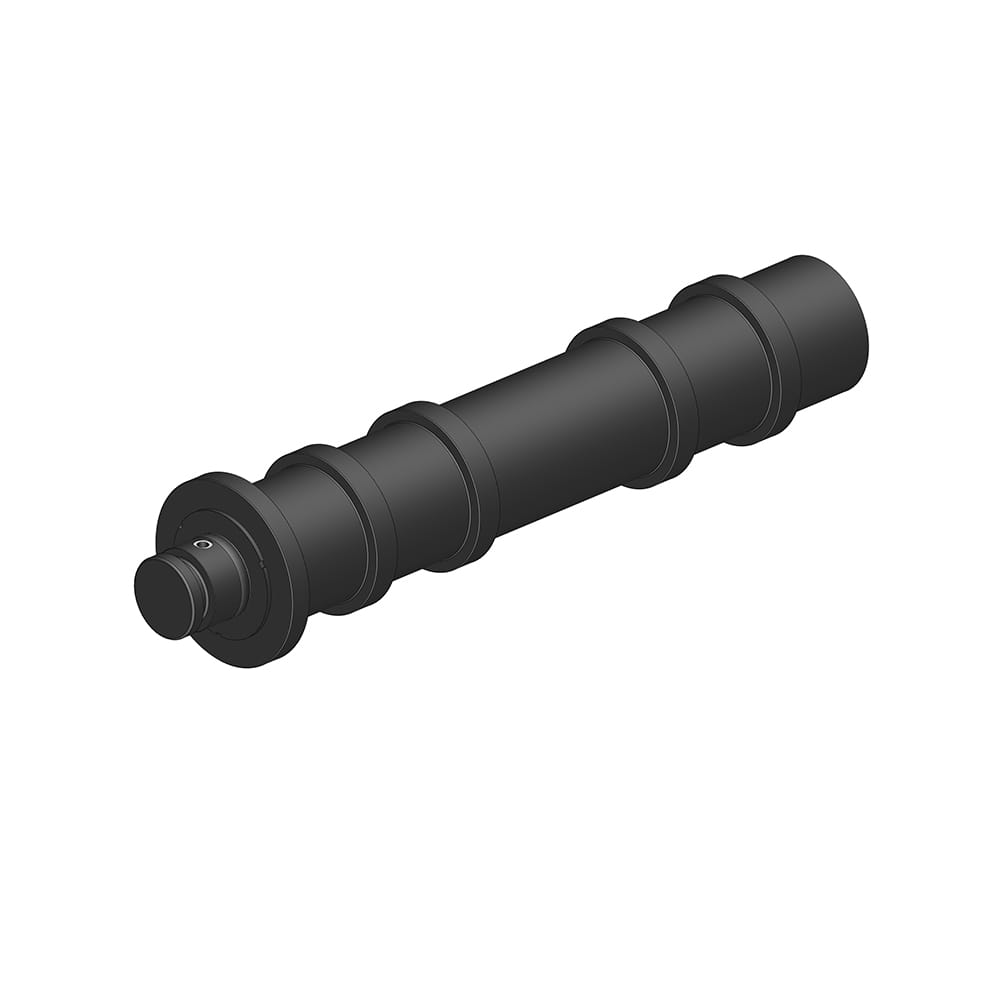
Pipe jacking is a trenchless pipeline installation method in which prefabricated pipe segments are pushed progressively through the ground from a launch shaft to a reception shaft, while a pipe jacking machine simultaneously excavates the ground at the tunnel face. The entire propulsive force that drives this system forward is generated by pipe jacking hydraulic cylinders positioned within the launch shaft and mounted against a reinforced concrete thrust wall. These cylinders are not peripheral components — they are the mechanical heart of the entire operation. Their output force, stroke control, pressure stability, and resistance to the underground environment directly determine whether a pipe jacking drive succeeds or encounters costly problems.
Unlike hydraulic cylinders used in surface-level construction equipment, pipe jacking hydraulic cylinders must perform under a uniquely demanding combination of conditions: high sustained thrust forces, extended continuous operation cycles, confined shaft working spaces, and constant exposure to soil, groundwater, and abrasive particulate matter. Meeting all of these demands simultaneously requires cylinders engineered specifically for this application — not adapted from general-purpose hydraulic equipment — with construction-grade pressure ratings, precision sealing systems, and contamination-resistant designs built in from the ground up.
The jacking force required to push a string of pipe segments through soil must overcome two primary resistances simultaneously: the face resistance at the cutting head of the pipe jacking machine, and the frictional resistance between the outer surface of the pipe string and the surrounding ground. As drive length increases, frictional resistance accumulates along the entire length of installed pipe, and the required jacking force can grow substantially — in long drives, total jacking loads can reach several thousand kilonewtons. The high pressure hydraulic cylinder used in pipe jacking must therefore be rated and constructed to sustain these forces consistently throughout the drive without performance degradation.
Operating pressures in pipe jacking hydraulic systems typically range from 250 bar to 400 bar (approximately 3,600 to 5,800 PSI), with peak pressures occurring when the system encounters harder ground conditions, changes in soil type, or when intermediate jacking stations are coordinating thrust across a long drive. A high pressure hydraulic cylinder designed for these applications incorporates heavy-wall cylinder barrels manufactured from high-strength steel alloys, precision-honed bore surfaces to minimize internal leakage, and high-capacity piston rod diameters that resist buckling under extreme compressive loads. The cylinder's ability to maintain its rated pressure without bypass or pressure drop is what engineers describe as pressure-retention capability — a property directly tied to seal quality, bore finish, and manufacturing tolerance control.
Pressure-retention performance is particularly critical during holds — periods in the jacking cycle when the advance is paused to lower and connect a new pipe segment. During these intervals, the hydraulic cylinders must hold the pipe string stationary against any tendency of the ground to push back or the pipe column to relax. A cylinder that allows pressure to bypass during these holds will permit pipe string drift, compromising the alignment accuracy of the installed pipeline and potentially causing structural damage to the pipe joints.
The underground environment of a pipe jacking launch shaft is inherently hostile to precision hydraulic components. As excavation proceeds, fine soil particles, sand, groundwater, and construction debris are constantly present in the working atmosphere. The piston rod of a hydraulic cylinder is particularly vulnerable: each extension and retraction cycle brings the polished rod surface out of the cylinder barrel and back, and any contaminant present on the rod surface at the moment of retraction will be drawn past the wiper seal and into the cylinder interior, where it will accelerate wear on the dynamic seals and eventually score the bore surface.
A purpose-engineered dustproof hydraulic cylinder addresses this risk through a multi-stage contamination exclusion system. The outermost protection layer is a heavy-duty wiper seal — also called a scraper seal — mounted at the rod gland and designed to physically remove bulk contaminants from the rod surface on each retraction stroke. Behind this sits a secondary rod seal that provides the primary hydraulic pressure boundary, now protected from contamination that has already been removed at the wiper stage. In demanding pipe jacking applications, some cylinder designs incorporate an additional labyrinth dust ring or felt ring between the wiper and the primary seal, creating multiple sequential barriers against particulate ingress.
The rod surface itself is also a critical factor in dustproof performance. Hard chrome plating or ceramic composite coatings applied to the piston rod provide a smooth, hard surface that resists particle adhesion and allows the wiper and rod seals to function effectively. A softer or rougher rod surface would allow abrasive particles to embed in the metal, creating a localized grinding action that destroys seals rapidly regardless of their quality. The combination of surface treatment on the rod and multi-layer sealing at the gland is what gives a properly specified dustproof hydraulic cylinder its resistance to the contaminated underground environment.
When selecting pipe jacking hydraulic cylinders for a specific project, engineers must evaluate several interdependent technical parameters. The table below outlines the principal specification categories and their practical significance:
| Specification | Typical Range | Engineering Significance |
| Operating Pressure | 250–400 bar | Determines maximum achievable jacking force output |
| Bore Diameter | 100–320 mm | Directly governs thrust force at a given pressure |
| Stroke Length | 1,000–2,500 mm | Must accommodate the length of one pipe segment per jacking cycle |
| Piston Rod Diameter | 70–200 mm | Governs compressive load capacity and buckling resistance |
| Rod Surface Treatment | Hard chrome or ceramic coating | Enables effective dustproof sealing and corrosion resistance |
| Seal Configuration | Multi-stage: wiper + rod seal + backup | Provides layered contamination exclusion in underground conditions |
| Cylinder Material | High-strength alloy steel | Sustains high-pressure loads without deformation or fatigue cracking |
Most pipe jacking setups in the launch shaft use not one but multiple pipe jacking hydraulic cylinders arranged symmetrically around the thrust ring — typically two, four, or six cylinders, depending on the pipe diameter and required thrust capacity. For the pipe string to advance in a straight line without rotation or misalignment at the joints, all cylinders in the array must extend synchronously, applying equal force and advancing at the same rate. Imbalanced thrust across the cylinder group will impose eccentric loads on the pipe joints and can cause angular deviation in the pipeline alignment — a costly problem to correct in mid-drive.
Operational stability in multi-cylinder configurations depends on both the hydraulic circuit design and the mechanical consistency of the individual cylinders. Proportional flow control valves or active synchronization systems in the hydraulic circuit manage flow distribution between cylinders in real time, compensating for minor differences in friction or load. At the cylinder level, tight manufacturing tolerances on bore diameter and seal friction ensure that each cylinder responds consistently to the same pressure input — a requirement that demands precision manufacturing, not just adequate pressure ratings.
Choosing the correct pipe jacking hydraulic cylinders for a project requires systematic evaluation of the specific site and operational conditions. The following factors should guide the specification process:
Even the most robustly specified pipe jacking hydraulic cylinders require structured maintenance practices to deliver reliable performance across an entire drive. The underground operating environment makes proactive maintenance more important than it would be for surface equipment — problems that develop underground are far more difficult and expensive to remedy mid-drive than they would be on the surface.
Properly specified and maintained pipe jacking hydraulic cylinders — combining the thrust capacity of a purpose-built high pressure hydraulic cylinder with the contamination resistance of a fully engineered dustproof hydraulic cylinder design — deliver the operational reliability, alignment accuracy, and service longevity that modern underground pipeline construction demands.
Your email address will not be published. Required fields are marked *
Marvelous Design Meets Rigorous Manufacturing
 Scissor Lift Aerial Platform Hydraulic Outrigger Cylinder
Function: Firmly Supports the Vehicle: Ensures stability during operation. The ball-head foot automatically levels on slopes, while the integrated balance valve...
 Scissor Lift Aerial Platform Hydraulic Steering Cylinder
Function: Connecting Chassis and Wheel Hub: Through hydraulic pressure, drives the piston rod to move, enabling precise wheel hub rotation. This ensures platfor...
 Boom Lift Aerial Platform Hydraulic Luffing Cylinder
Function: Adjust the angle of the telescopic arm to flexibly position the work platform at various heights and positions, meeting diverse aerial work requiremen...
 Boom Lift Aerial Platform Hydraulic Telescopic Cylinder
Function: Adjust the length of the arm to allow the aerial work platform to lift and move flexibly, ensuring range and height requirements.
 Boom Lift Aerial Platform Hydraulic Frame Leveling Cylinder
Function: Automatically adjust the chassis at the bottom of the platform to a level state, ensuring stable and wobble-free support in different terrains and wor...
 Boom Lift Aerial Platform Hydraulic Bridge Extension Cylinder
Function: An important design that enhances adaptability and working range. This function allows the platform to widen its chassis under specific conditions to ...
Copyright © by Zhejiang Huanfeng Machinery Co., Ltd. Rights Reserved.
