 English
 中文简体
中文简体 русский
 Español
 Português
 عربى
عربىProduct Consultation
Your email address will not be published. Required fields are marked *
Content
The operational demands placed on a Hydraulic Cylinder for Scissor Lift Aerial Platform require an uncompromising approach to sealing integrity. In aerial environments, even minor internal leakage can translate into noticeable platform drift, which compromises both positioning accuracy and operator confidence. Modern sealing assemblies utilize multi-lip polyurethane compounds specifically engineered to withstand dynamic pressure fluctuations while maintaining friction coefficients that prevent stick-slip motion. These materials are selected based on rigorous compatibility testing with anti-wear hydraulic oils, ensuring that chemical degradation does not occur over extended duty cycles or during exposure to extreme temperature variations. The rod wiper design incorporates dual-stage cleaning mechanisms that actively remove particulate contamination during retraction, thereby protecting the primary pressure seal from abrasive wear. Engineers must also account for thermal expansion differentials between the cylinder barrel and piston rod, which can alter clearance gaps under harsh ambient conditions. Implementing backup rings made from high-modulus thermoplastics effectively prevents extrusion during pressure spikes, a common occurrence during sudden load shifts or emergency stops. Routine inspection protocols should focus on early detection of micro-leakage around gland areas, as prompt intervention prevents catastrophic failure and extends component lifespan significantly across demanding industrial schedules.
Leakage in scissor lift applications rarely stems from a single point of failure but rather from a combination of surface finish degradation, seal compression set, and improper installation practices. The piston seal must accommodate both high-pressure extension forces and the vacuum conditions generated during rapid retraction. Advanced sealing configurations often integrate spring-energized PTFE elements that maintain constant contact pressure against cylinder walls, regardless of temperature variations or wear progression. Surface finishing on the piston rod typically targets a Ra value below 0.2 micrometers, combined with hard chrome plating or nickel-based coatings to resist pitting and corrosion. When maintenance technicians replace seals, they must strictly adhere to torque specifications for gland nuts and utilize proper alignment tools to avoid nicking the sealing lips. Neglecting these procedural details introduces immediate failure pathways that compromise the entire lifting mechanism and necessitate costly downtime.
Preventing pressure loss requires systematic attention to fluid cleanliness, component alignment, and operating parameters. Contaminated hydraulic fluid accelerates abrasive wear on sealing surfaces, creating micro-grooves that compromise barrier integrity. Installing multi-stage filtration systems rated to ISO 4406 cleanliness standards significantly reduces particulate ingress and prolongs seal viability. Additionally, improper cylinder mounting angles introduce side-loading forces that concentrate stress on one side of the piston seal, leading to asymmetric wear and premature failure. Technicians should utilize precision laser alignment tools during installation to ensure the cylinder axis remains perfectly parallel to the scissor linkage pivot points. Monitoring operating temperatures is equally critical, as sustained exposure above 80 degrees Celsius accelerates elastomer aging and reduces tensile strength. Implementing thermal relief loops or auxiliary cooling circuits maintains fluid viscosity within optimal ranges, ensuring consistent sealing performance throughout extended work shifts.
The mechanical geometry of scissor linkages inherently amplifies vertical displacement relative to cylinder stroke length, meaning the platform descending speed far exceeds that of the cylinder itself. This kinematic multiplication effect demands precise hydraulic control to prevent uncontrolled drops or oscillatory movements. A well-calibrated lifting system must operate in tandem with flow-regulating components that manage the volume of oil exiting the cylinder during descent. Without adequate throttling, gravitational forces acting on the platform load can cause the piston rod to retract faster than the system can safely dissipate energy. Smooth movement of the piston rod directly impacts platform stability, particularly when workers are positioned at maximum height or handling sensitive equipment. The integration of proportional damping circuits allows operators to modulate descent velocity continuously, eliminating the jerky motion commonly associated with fixed-orifice check valves. Engineers achieve this balance by matching cylinder bore diameter to the expected load distribution while selecting appropriate meter-out configurations that restrict return flow without generating excessive backpressure.
Achieving consistent descent profiles requires a systematic approach to fluid dynamics within the lifting circuit. The relationship between cylinder extension velocity and platform drop rate can be modeled using trigonometric functions derived from the scissor arm angles. As the platform lowers, the leverage ratio changes continuously, necessitating adaptive control strategies. Modern implementations utilize electronically compensated flow dividers that adjust orifice areas in real time based on load cell feedback and position sensors. This ensures uniform speed across the entire travel range, preventing sudden acceleration when the linkage passes through mechanical dead centers. Maintenance personnel should verify calibration settings during quarterly inspections and replace worn valve spools that exhibit increased internal leakage. Regular testing of return line pressure helps identify degraded damping performance before it manifests as visible platform oscillation or operator discomfort.
| Control Method | Response Time | Load Sensitivity | Maintenance Frequency |
| Fixed Orifice Valve | Low | High | Quarterly |
| Proportional Flow Valve | High | Low | Semi-Annually |
| Load-Sensing Circuit | Medium | Medium | Annually |
| Electronic Damping System | Instant | Negligible | Bi-Annually |
The cylinder safety factor and stability are crucial, as they directly relate to worker safety operating at significant elevations. Industry standards typically mandate a minimum safety factor of four times the rated working pressure, though specialized applications may require five or six times depending on environmental hazards and load dynamics. Structural reliability begins with fatigue-resistant barrel construction, usually fabricated from cold-drawn seamless steel tubing that undergoes honing to achieve optimal internal geometry. The piston rod is manufactured from high-yield alloy steel and subjected to shot peening processes that introduce compressive residual stresses, dramatically improving resistance to bending and buckling under eccentric loads. Mounting interfaces must be designed to distribute stress evenly across the cylinder base and eye clevis, preventing localized deformation that could lead to seal extrusion or rod misalignment. Engineers perform finite element analysis during the design phase to identify potential weak points and validate load distribution under worst-case scenarios, including side-loading conditions and impact shocks from uneven terrain.
Comprehensive load testing protocols ensure that every unit meets or exceeds regulatory requirements before deployment. Pressure testing involves subjecting the cylinder to one and a half times its maximum operating pressure for a sustained duration while monitoring for permanent deformation or external leakage. Proof load testing verifies structural integrity by applying static forces equivalent to maximum anticipated platform weight, including safety margins for dynamic impacts. Manufacturers must maintain detailed traceability records that include material certifications, heat treatment logs, and dimensional inspection reports. These documentation practices facilitate rapid root-cause analysis in the rare event of field failures and support continuous improvement initiatives. Compliance with international standards such as EN 280 or ANSI A92 provides independent verification of design adequacy and manufacturing quality control, giving fleet operators confidence in long-term reliability and regulatory compliance.
Additionally, valves with various functions can be configured to meet customer needs, allowing manufacturers to tailor hydraulic behavior to specific operational profiles. Standard configurations often include counterbalance valves that prevent uncontrolled descent in the event of hose rupture, combined with holding valves that lock the cylinder position when the control system is idle. Advanced installations may integrate pilot-operated check valves with adjustable cracking pressures, enabling fine-tuning of descent initiation force without compromising emergency lowering capabilities. Flow control cartridges can be paired with pressure-relief modules to create compact manifold blocks that reduce plumbing complexity and potential leak points. Technicians responsible for field service appreciate modular valve architectures that permit individual component replacement without dismantling the entire hydraulic circuit. This configurability ensures that Hydraulic Cylinders for Aerial Work can adapt to diverse application requirements, from precision glass installation to heavy-duty industrial maintenance.
The synergy between counterbalance and holding valves forms the backbone of reliable scissor lift operation. Counterbalance mechanisms maintain backpressure on the cylinder return line, effectively resisting gravitational forces that would otherwise accelerate platform descent. These valves typically feature direct-acting pilot stages that open proportionally to system pressure, ensuring smooth operation regardless of load variations. Holding valves activate automatically when control pressure drops below a predetermined threshold, mechanically blocking fluid flow and securing the platform at the current elevation. This dual-action approach eliminates the need for external mechanical locks while providing fail-safe protection against hydraulic line failures. When properly calibrated, these systems significantly reduce accident risk and enhance overall system predictability during critical elevation tasks.
Your email address will not be published. Required fields are marked *
Marvelous Design Meets Rigorous Manufacturing
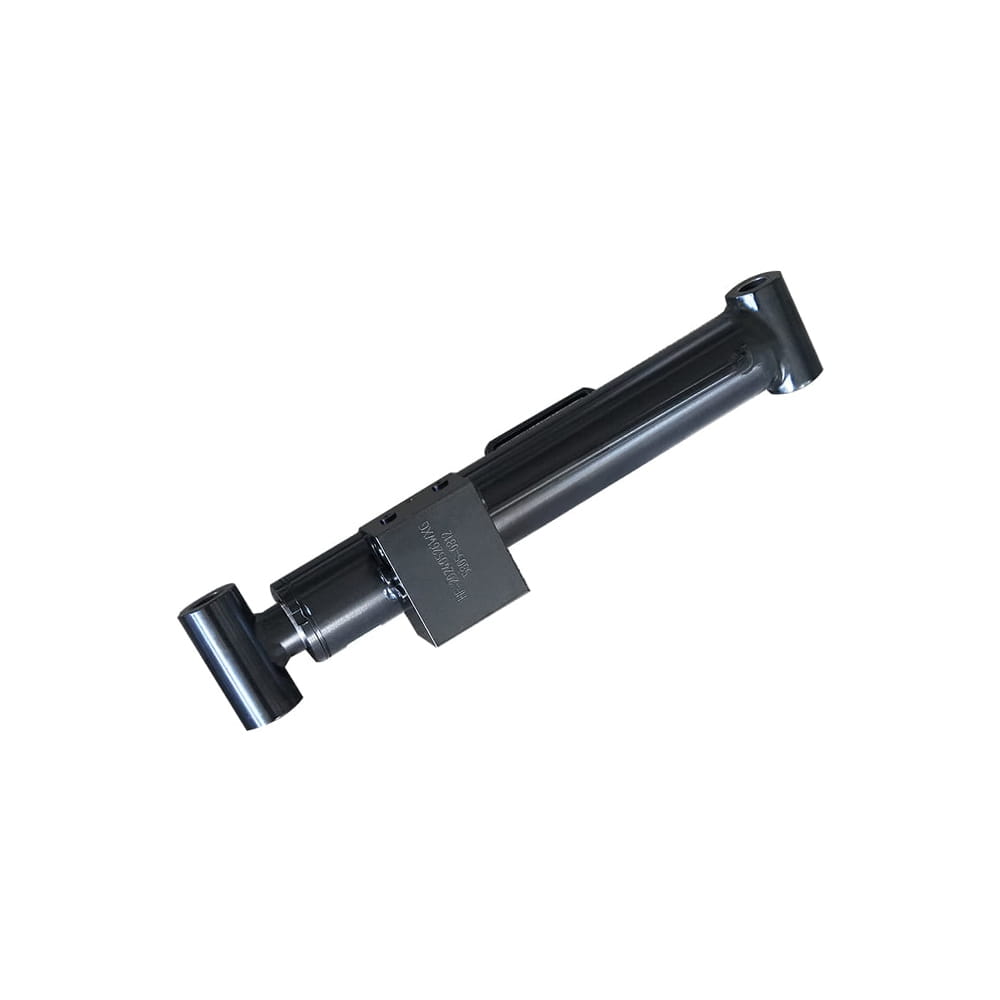
 Scissor Lift Aerial Platform Hydraulic Outrigger Cylinder
Function: Firmly Supports the Vehicle: Ensures stability during operation. The ball-head foot automatically levels on slopes, while the integrated balance valve...
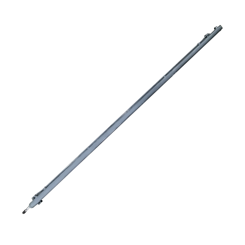
 Scissor Lift Aerial Platform Hydraulic Steering Cylinder
Function: Connecting Chassis and Wheel Hub: Through hydraulic pressure, drives the piston rod to move, enabling precise wheel hub rotation. This ensures platfor...
 Boom Lift Aerial Platform Hydraulic Luffing Cylinder
Function: Adjust the angle of the telescopic arm to flexibly position the work platform at various heights and positions, meeting diverse aerial work requiremen...
 Boom Lift Aerial Platform Hydraulic Telescopic Cylinder
Function: Adjust the length of the arm to allow the aerial work platform to lift and move flexibly, ensuring range and height requirements.
 Boom Lift Aerial Platform Hydraulic Frame Leveling Cylinder
Function: Automatically adjust the chassis at the bottom of the platform to a level state, ensuring stable and wobble-free support in different terrains and wor...
 Boom Lift Aerial Platform Hydraulic Bridge Extension Cylinder
Function: An important design that enhances adaptability and working range. This function allows the platform to widen its chassis under specific conditions to ...
Copyright © by Zhejiang Huanfeng Machinery Co., Ltd. Rights Reserved.
