
 English
 中文简体
中文简体 русский
 Español
 Português
 عربى
عربىProduct Consultation
Your email address will not be published. Required fields are marked *
Content
Hydraulic cylinders for pipe jacking machines are not standard industrial actuators; they are the primary thrust generators that push concrete or steel pipes through the earth with millimeter-level precision. Their core working principle is to convert the hydraulic power pack's high-pressure fluid energy into a controlled, massive linear force, often exceeding 300 tonnes per cylinder, to overcome the friction and cutting resistance between the pipe string and the surrounding soil. These cylinders operate as a synchronized tandem set within the main jacking station, advancing the entire pipe string incrementally with each stroke. Their ability to maintain a constant push force without drifting under load is what prevents pipe string relaxation, which could cause ground settlement or joint damage.
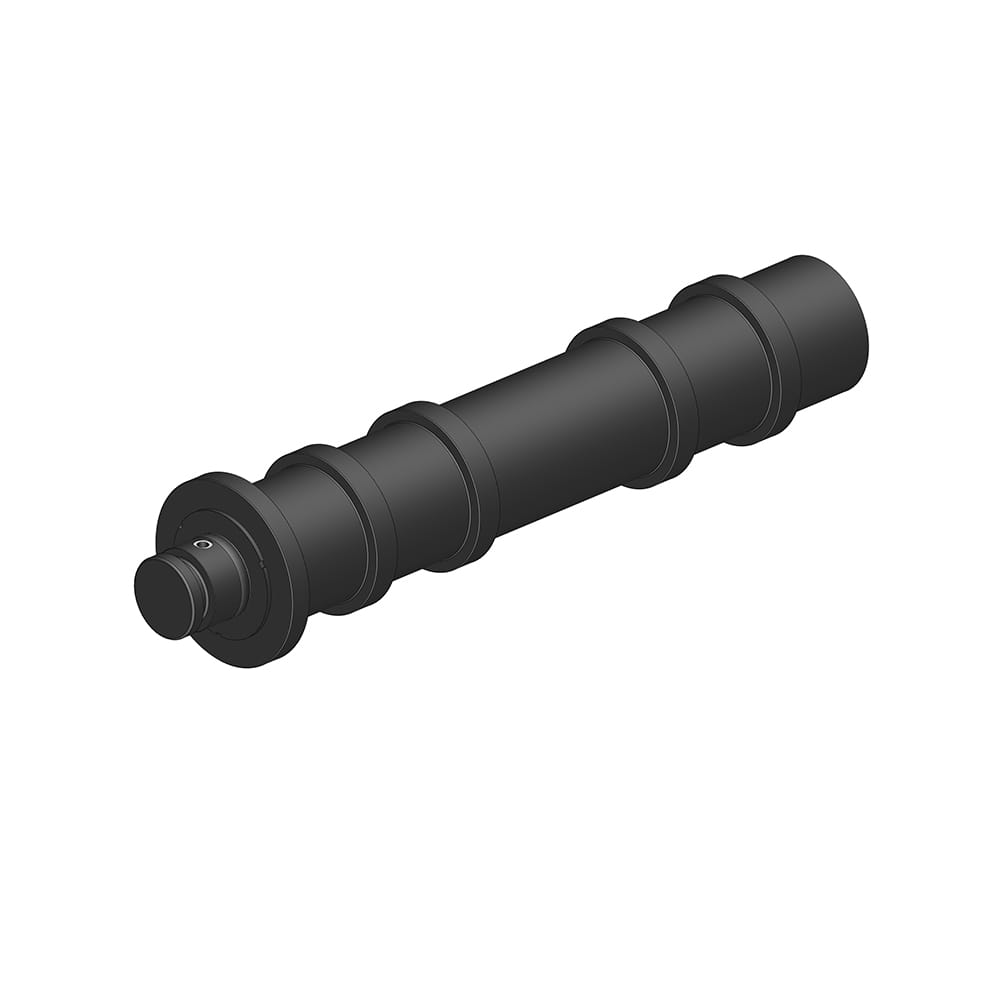
Pipe jacking demands sustained operation at the upper limits of hydraulic working pressure, typically in the range of 350 bar to 420 bar. This is significantly higher than general industrial hydraulics. The cylinder barrel is not a standard honed tube but is manufactured from a high-yield-strength steel, typically 27SiMn or ST52.3, with a wall thickness calculated to handle the internal pressure with a safety factor of 3:1 or higher. The end caps are precisely welded using a multi-pass submerged arc process, followed by full volumetric ultrasonic inspection to certify the absence of weld defects. A barrel that can survive 1.5 times the rated working pressure in a hydrostatic proof test without any permanent deformation is the minimum acceptance standard, ensuring that a sudden pressure spike from encountering an underground obstruction does not result in a catastrophic barrel rupture.
In a multi-cylinder jacking station, pressure retention defines the quality of the installation. If one cylinder exhibits internal bypass, the entire thrust frame becomes unbalanced, a condition that can steer the pipe string off its designated alignment. The pressure-holding integrity is defined by the piston seal design, typically a tandem arrangement of a PTFE-based primary seal with an O-ring energizer, backed up by a nylon wear ring and a buffer seal that protects the primary seal from pressure spikes.
A definitive quality metric for these cylinders is their performance in a static pressure hold test. A certified cylinder, when pressurized to its maximum working pressure and valved off, must exhibit a pressure decay of less than 5 bar over a 5-minute period. Any leakage across the piston seal is a direct loss of jacking force, resulting in the micro-relaxation of the pipe string. Over the course of a 100-meter drive involving hundreds of stroke cycles, a leaking cylinder introduces cumulative alignment errors that can cause pipe joint over-compression and gasket failure. The piston seal is therefore not just a sealing element; it is a key contributor to the accuracy of the tunnel alignment.
The underground environment of a jacking shaft is one of the most contamination-aggressive conditions for hydraulic equipment. A single particle of silica sand, measuring 50 micrometers, that embeds in a rod seal can machine a micro-scratch into the chrome-plated rod with every stroke, creating a permanent leakage path. The dustproof system is a multi-stage defense integrated into the cylinder head gland.
The first line of defense is an externally mounted, robust wiper seal with a secondary lip. The primary lip faces outward and has a sharp, acute edge that scrapes bonded mud and large particles off the rod during retraction. The secondary lip faces inward and captures any contaminant film that bypasses the primary wiper. Beneath this wiper, a rod buffer seal resides, which meters a controlled oil film onto the rod for lubrication while preventing any residual fine particles from reaching the main rod seal. For slurry-type pipe jacking machines, this system is further enhanced with a pressurized oil cavity between the wiper and the rod seal, maintained at a low positive pressure of 0.5 bar. This internal positive pressure permanently prevents the ingress of groundwater and sub-micron slurry particles, even when the cylinder is fully submerged in a flooded shaft.
A pipe jacking machine typically uses a set of four or more cylinders arranged symmetrically around the pipe axis. The thrust must be perfectly distributed to avoid point-loading a concrete pipe and causing a spalling fracture. Synchronization is achieved through a flow-divider valve or a closed-loop electro-hydraulic control system. The table below outlines the critical performance parameters that a set of jacking cylinders must satisfy as a synchronized unit.
| Synchronization Parameter | Specification | Consequence of Non-Compliance |
|---|---|---|
| Cylinder-to-Cylinder Stroke Deviation | ≤ 2.0 mm over full stroke | Thrust frame skew; pipe edge loading |
| Pressure Differential Between Cylinders | ≤ 5% of setpoint | Uneven thrust ring distribution |
| Extension Speed Uniformity | ±2% of commanded velocity | Intermittent stick-slip pipe movement |
| Accumulated Stroke Count Discrepancy | Zero over a complete drive | Progressive thrust ring rotation |
The piston rod is the only dynamic component exposed to the external environment and is the most vulnerable point of the cylinder. The rod surface is not simply chrome-plated; it undergoes a specific surface engineering process tailored for underground abrasion. The base steel, typically C45 or 42CrMo4, is induction hardened to a case depth of 1.5mm to 2.0mm achieving a surface hardness of HRC 55-60. This hardened core provides mechanical support for the hard chrome plating applied on top. The plating is a duplex or micro-cracked chrome with a thickness of 0.08mm to 0.12mm per side, ground and polished to a final surface finish of Ra ≤ 0.2 µm. The micro-cracked chrome structure is critical; it provides micro-reservoirs that retain oil for lubricating the wiper and rod seal interface, extending seal life in the dry, abrasive conditions of a jacking shaft.
A pipe jacking cylinder cannot be easily extracted for repair once a drive has commenced. Preventative maintenance is therefore focused on what is accessible: the exposed rod surface and the external wiper seal. Before every retraction cycle, the operator must visually inspect the rod for any adhered grit and wipe it clean with a lint-free cloth. The external wiper seal must be manually cleaned of accumulated mud cake. A critical pre-operational check is the static drift test under the no-load condition of the thrust ring, performed at the start of each shift. Any measurable rod creep with the pump offline indicates internal seal bypass that will only worsen as the drive continues. The wiper seal is a service-replaceable item that can be changed in situ by unscrewing the gland nose ring, a task that should be scheduled every 500 operating hours in abrasive strata conditions.
Your email address will not be published. Required fields are marked *
Marvelous Design Meets Rigorous Manufacturing
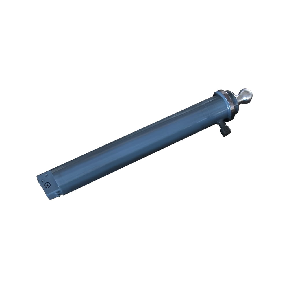 Scissor Lift Aerial Platform Hydraulic Outrigger Cylinder
Function: Firmly Supports the Vehicle: Ensures stability during operation. The ball-head foot automatically levels on slopes, while the integrated balance valve...
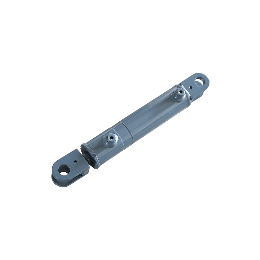 Scissor Lift Aerial Platform Hydraulic Steering Cylinder
Function: Connecting Chassis and Wheel Hub: Through hydraulic pressure, drives the piston rod to move, enabling precise wheel hub rotation. This ensures platfor...
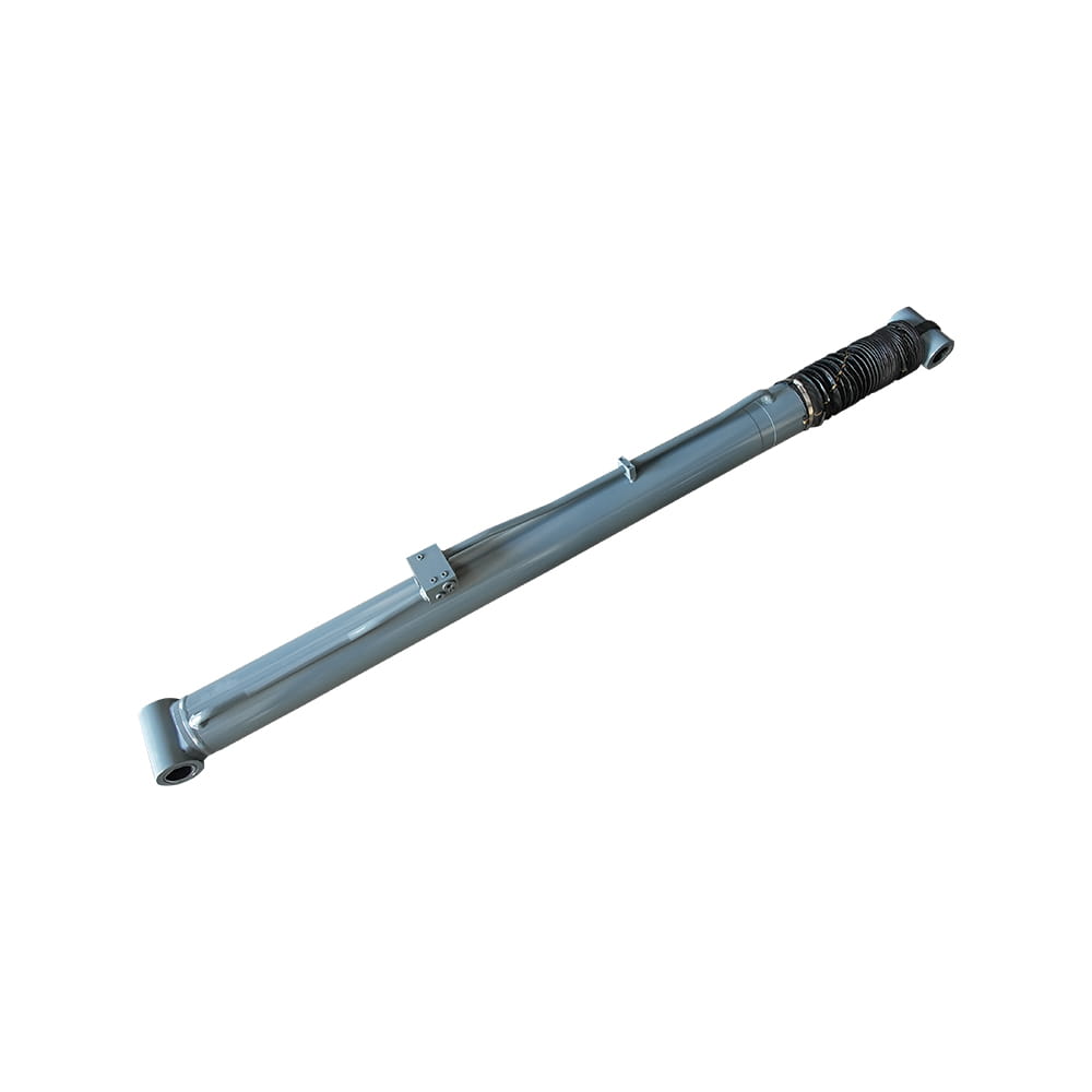 Boom Lift Aerial Platform Hydraulic Luffing Cylinder
Function: Adjust the angle of the telescopic arm to flexibly position the work platform at various heights and positions, meeting diverse aerial work requiremen...
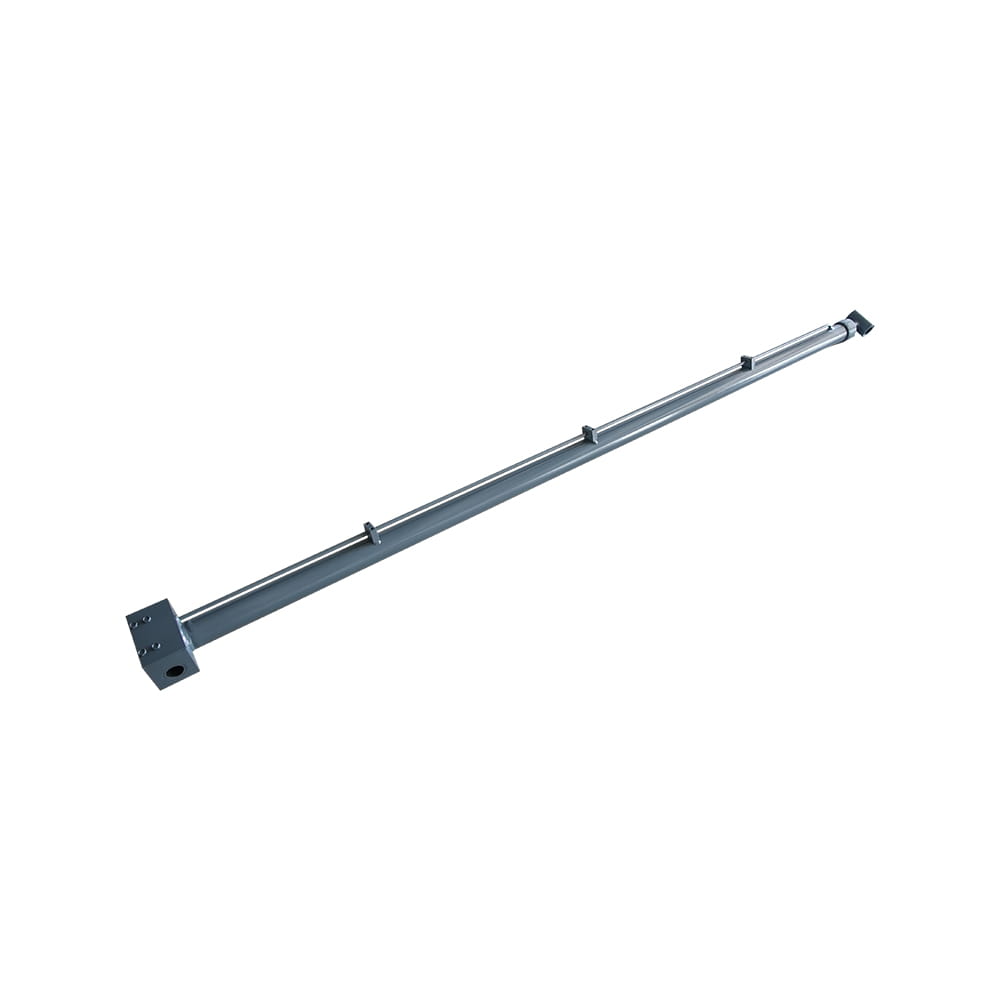 Boom Lift Aerial Platform Hydraulic Telescopic Cylinder
Function: Adjust the length of the arm to allow the aerial work platform to lift and move flexibly, ensuring range and height requirements.
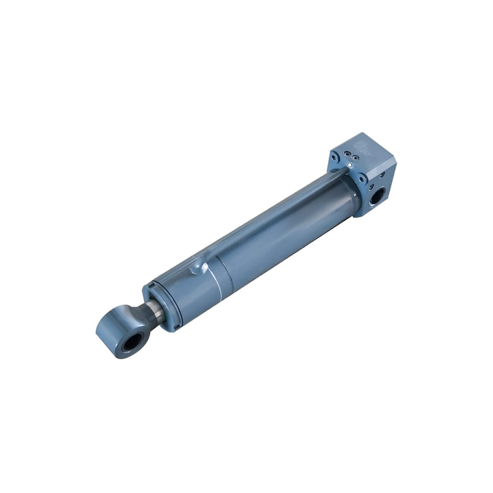 Boom Lift Aerial Platform Hydraulic Frame Leveling Cylinder
Function: Automatically adjust the chassis at the bottom of the platform to a level state, ensuring stable and wobble-free support in different terrains and wor...
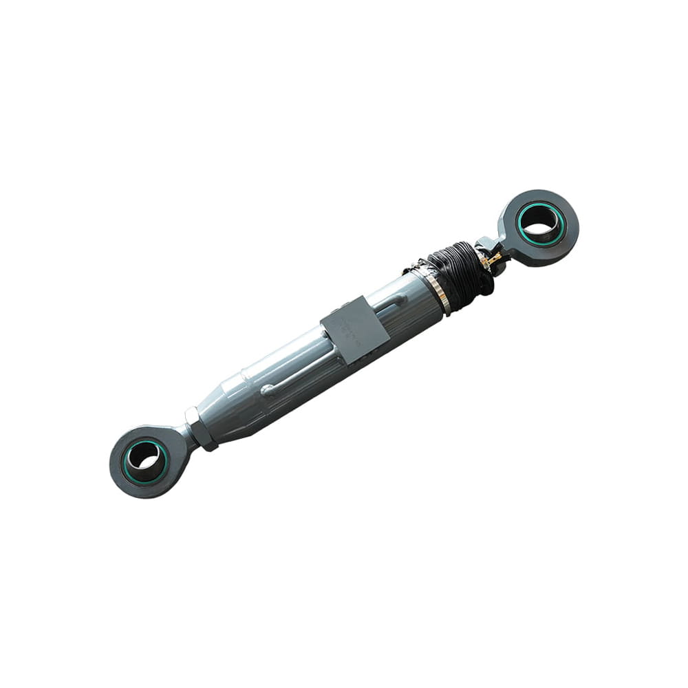 Boom Lift Aerial Platform Hydraulic Bridge Extension Cylinder
Function: An important design that enhances adaptability and working range. This function allows the platform to widen its chassis under specific conditions to ...
Copyright © by Zhejiang Huanfeng Machinery Co., Ltd. Rights Reserved.
